
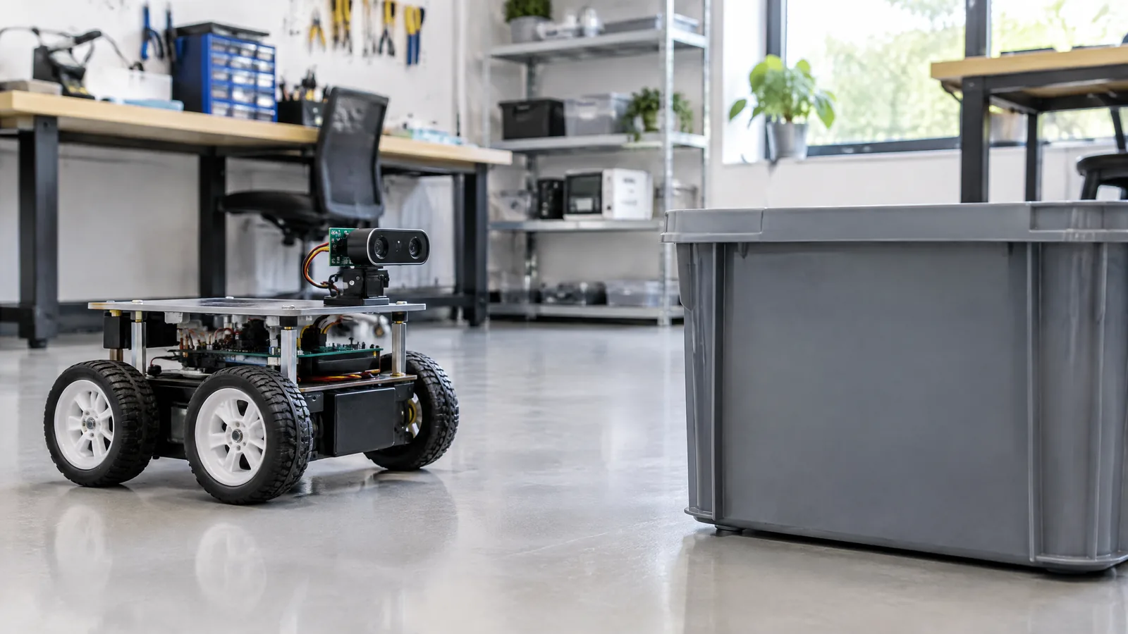
A small robot can still misjudge a wall when a simple proximity module only tells it that reflected light crossed a threshold. A Time-of-Flight (ToF) distance sensor measures the travel time of emitted infrared light returning from a target, giving a distance reading that can support obstacle detection, bin sensing, approach wake-up or touch-free interaction when the final enclosure and target are tested.
This article is part of the computer hardware technology guide library.
Key takeaways
A ToF distance sensor actively emits invisible infrared light and estimates range from the returned signal; it is not an ultrasonic sensor and it is not just a passive light detector.
A controller normally reads an integrated ToF device over I²C, while a breakout board may add regulators, pull-ups or level shifting. Those board features are optional external components, not part of every physical sensor.
Field of view, target reflectance, ambient light, cover-glass crosstalk, timing settings and multiple-sensor interference can change the result. Validate the assembled product, not only an open-board demo.
- Use a ToF sensor when the application needs a compact optical distance measurement or zone-based ranging.
- Treat a model’s advertised range and frame rate as device-specific test conditions, not universal promises.
- Keep safety-critical motion decisions independent of a single unverified distance reading.
What is a Time-of-Flight (ToF) distance sensor?
A Time-of-Flight (ToF) distance sensor sends a short burst of infrared light towards a scene and detects photons that return after reflecting from a target. Because light takes a measurable time to travel out and back, the device can calculate an absolute distance. In a typical integrated module, the emitter, receiving array and processing electronics work together; the host receives a processed measurement rather than timing the light pulse itself.
This is different from a basic reflective IR sensor, which may report that reflected light passed a threshold. It is also different from an ultrasonic sensor, which sends sound and measures an echo. A ToF device is an active optical sensor: it needs its own optical path, and its result depends on the target, optics and operating conditions.
How does ToF ranging work?
Inside a representative direct-ToF device, an infrared VCSEL emitter sends pulses and a SPAD receiving array detects returning photons. The sensor’s internal ranging core and firmware process the signal, reject weak or invalid results, and expose a distance through a digital interface. ST’s VL53L0X datasheet describes a ranging phase in which several 940 nm infrared pulses are emitted, reflected by the target and detected by the receiving array.
For a beginner using an Arduino-compatible controller, the practical path is usually I²C: connect the breakout’s documented power, ground, SDA and SCL lines, install the model’s driver or library, then read the distance and status. The exact voltage, address, pull-ups and shutdown pin depend on the device or breakout. The sensor itself is the optical and processing component; an Arduino board, carrier PCB, wiring and software library are separate parts.
A reading can be polled or delivered through an interrupt on supported devices. Filtering, hysteresis or averaging can make an application decision steadier, but they cannot repair a poor optical installation or turn an invalid reading into a guaranteed measurement.
- Physical sensor: emitter, receiver array, optics and internal processing.
- Optional carrier or breakout: PCB, regulator, connectors, pull-up resistors and sometimes level shifting.
- External instrument or controller: Arduino-compatible board, STM32 board, computer or other host running the driver.
Useful applications in a robot or prototype
For a small robot, a forward-facing ToF sensor can provide a measured distance for a slow obstacle-response experiment. A multizone device can divide the scene into zones, helping a prototype distinguish an object on one side from an object on the other. This is more informative than a single threshold, but the application still needs a tested decision rule and a fallback for missing or weak measurements.
A downward-facing sensor can support bin or container fill estimation when the surface, opening and mounting geometry are stable. A short-range sensor can also wake a display or device when someone approaches, or provide distance input for a touch-free interface. These are sensing functions, not proof of identity, intention or safety.
ST lists robotics uses such as obstacle detection, small-object detection, cliff and collision avoidance, 3D mapping and SLAM for its ToF portfolio. Those system-level uses require suitable optics, software, calibration and additional sensors; a beginner module alone does not deliver a complete navigation or safety system.
- Obstacle awareness: use a measured range and explicit invalid-reading handling.
- Bin or level sensing: test the actual contents, opening and mounting angle.
- Approach wake-up: choose a threshold and test movement, lighting and false triggers.
- Gesture or distance interaction: use zones or repeated samples only after testing the intended hand position.
What can change the reading?
Field of view is part of the measurement design. A target outside the active detection volume may not be reported, while a wide field of view can include a nearby edge or background object. The VL53L5CX, for example, can output 4×4 or 8×8 zones and has a device-specific optical field of view; its datasheet notes that the effective detection volume depends on target distance, reflectance, ambient light, resolution, ranging mode and integration time. Do not copy a model’s angles to another sensor.
A cover window can reflect some of the emitter’s light back into the receiver. ST calls this cover-glass crosstalk. Its guidance says crosstalk can be significant at short distances and may require calibration when a protective window is used. Therefore, test the final cover, gasket, opening and sensor tilt together. A bare breakout reading is not enclosure validation.
Target colour and reflectance, sunlight or strong indoor lighting, surface angle and object size also matter. Manufacturer test tables are tied to stated targets and conditions. Use them to understand the device, not to promise the same range in every Indian room, corridor or outdoor scene.
- Mount the sensor at the final height and angle.
- Test dark, light, shiny, textured and angled targets where relevant.
- Check the complete cover glass or plastic window for false near readings.
- Record valid, weak-signal and no-target states separately.
- If more than one sensor is used, follow the model’s sequencing, shutdown and address guidance.
Choosing a ToF sensor for Arduino projects
Start with the decision your prototype must make: one distance, several zones, a near-approach trigger or a wider scene description. Then compare the sensor’s documented range, field of view, zone count, interface, supply rails, update rate, mounting constraints and software support. A single-zone device can be simpler; a multizone sensor may provide more spatial information but needs more configuration and processing.
Check whether the board is 5 V-tolerant or needs level conversion. A sensor may use 2.8 V or 3.3 V rails even when the carrier board accepts a wider input. Confirm I²C pull-ups and address behaviour before adding modules. For multiple identical devices, a model may need separate shutdown control so addresses can be changed one at a time; this is an integration detail, not a universal Arduino rule.
Avoid selecting by a headline maximum distance alone. Ask whether the target fills the field of view, whether the reading must work in daylight, and what the enclosure does to the optics. Build the test around the real target and the real software state.
Is a ToF distance sensor the same as an IR sensor?
It uses infrared light, but an integrated ToF distance sensor measures the light travel time and reports range. A basic reflective IR module may only report a thresholded reflection, so the two should not be treated as interchangeable.
Can I use a ToF distance sensor with Arduino?
Many ToF modules can be connected to an Arduino-compatible controller through I²C, but the required voltage, pull-ups, address handling and library depend on the exact sensor and carrier board. Follow that model’s documentation.
Does ToF work in sunlight?
It can work in ambient light within the device’s specified conditions, but strong ambient light can reduce detection performance or range. Test the actual installation outdoors or near windows rather than assuming the indoor result will transfer.
Why does a ToF sensor show a false close object behind a cover?
Reflections inside the cover can create cover-glass crosstalk. The window geometry and sensor model may require a documented calibration or compensation procedure, especially at short distances.
Can one ToF sensor make a robot safe?
No. A single reading can be missing, weak or affected by geometry and materials. Safety-critical motion needs a suitably engineered system with validated sensing, control, limits and independent safeguards.
About the image
AI-generated editorial illustration; not an actual product or mission photograph.
Source notes
Reporting record
techduopulse stores source destinations privately. Public notes remain non-clickable so every visitor journey stays on this website.
Source note: STMicroelectronics Time-of-Flight sensors overview
Primary source · Direct ToF integration; robotics, smart-device and industrial applications; low-light and target considerationsSource note: STMicroelectronics VL53L0X datasheet
Primary source · 940 nm emitter, SPAD receiver, ranging phase, I²C interface, polling/interrupt and crosstalk processingSource note: STMicroelectronics VL53L5CX datasheet
Primary source · 4x4/8x8 zones, optical field of view, target/ambient-light conditions, cover-glass compensation and model-specific specificationsSource note: STMicroelectronics UM2884 integration guide
Primary source · Host/driver architecture, I²C address changes for multiple sensors, cover-glass crosstalk calibration and optional pluginsInitial 15 October 2026 India-facing ToF explainer. Distinguishes the physical optical sensor from optional carrier boards, controllers and software; grounds ranging, I²C, multizone, field-of-view and cover-glass guidance in STMicroelectronics primary documents; and avoids universal range or safety claims.


