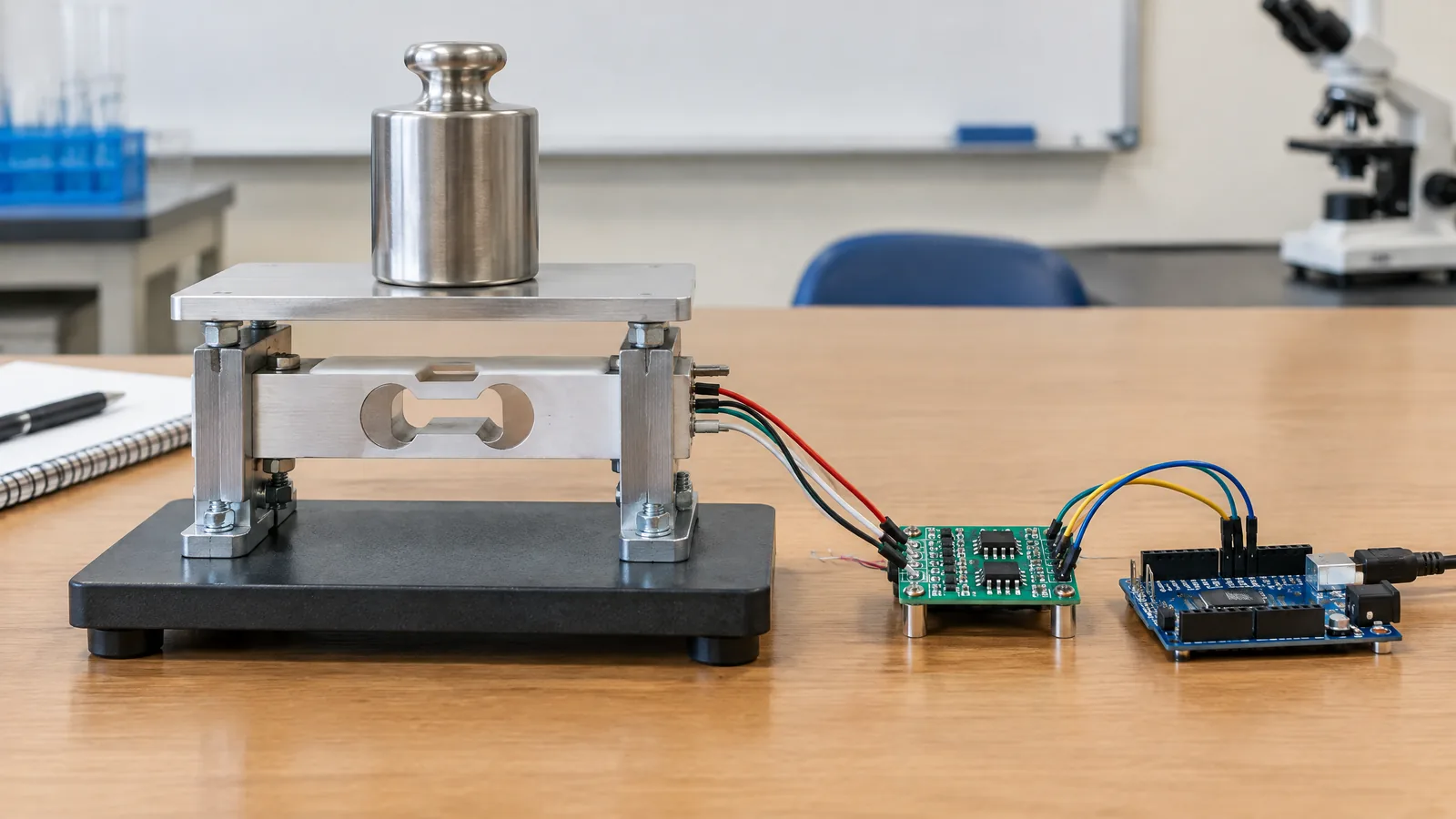
A battery monitor can show voltage and still miss the question that matters: how much current is actually flowing into or out of the load? A shunt-resistor current monitor measures that current indirectly by reading the small voltage across a precision resistor, then using an amplifier or monitor IC and an ADC to turn it into useful current, power and energy readings.
This article is part of the computer hardware technology guide library.
Key takeaways
The physical sensing element is a precision resistor placed in series with the current path; the rest of the circuit conditions and interprets its voltage.
Current is derived from Ohm’s law: I = Vshunt / Rshunt. A larger resistor gives a larger signal but wastes more voltage and power.
High-side sensing leaves the load ground undisturbed but needs a front end that can handle the rail’s common-mode voltage. Low-side sensing is simpler at the input but inserts the shunt into the ground path.
Kelvin connections, filtering, a suitable input range and calibration matter more than simply choosing a very small resistor.
- Use a rated, low-inductance shunt for the expected current and heat.
- Keep force-current paths separate from sense traces.
- Treat mains and high-energy battery systems as a qualified engineering job, not as a low-voltage hobby circuit.
What a shunt-resistor current monitor actually measures
A shunt resistor is a deliberately small resistance inserted in series with a load, charger or battery path. Current through it creates a voltage drop. If the resistor is 10 milliohms and the current is 2 amperes, the ideal differential voltage is 20 millivolts. A current-sense amplifier, difference amplifier, instrumentation amplifier or dedicated power monitor can scale that small differential signal for an ADC or microcontroller.
The resistor is the physical sensor. An amplifier is not the sensor itself; it is an optional analogue front end. An ADC or digital current-monitor IC is an instrument that converts or reports the conditioned measurement. A microcontroller can calculate current, power and accumulated charge, but it does not sense current without the shunt and its measurement path.
For a simple estimate, use I = Vshunt / Rshunt. To estimate instantaneous electrical power, multiply measured current by the measured bus voltage. Accumulated energy then requires sampling over time and adding the interval results. These calculations describe an estimate, not a guarantee of battery state of charge or battery safety.
High-side or low-side shunt sensing?
In a low-side circuit, the shunt sits between the load return and ground. The amplifier inputs operate near ground, which can simplify common-mode requirements. The cost is that the load ground is no longer exactly the supply ground; the shunt voltage appears in that return path. A fault or alternate return path can also bypass a low-side monitor.
In a high-side circuit, the shunt sits between the positive bus and the load. The load ground stays connected directly to the system ground, and the arrangement can reveal downstream short-to-ground conditions. The amplifier must instead tolerate the bus common-mode voltage while resolving the much smaller voltage difference across the resistor.
For a low-voltage battery, charger or load monitor, choose the arrangement based on grounding, fault visibility, bidirectional-current needs and the front end’s specified common-mode range. Do not infer suitability from the battery voltage alone: the amplifier’s input limits, transients and supply arrangement must match the actual circuit.
| Choice | Main advantage | Main limitation |
|---|---|---|
| Low-side shunt | Input common-mode voltage is near ground | Adds voltage to the ground return and can be bypassed by another return path |
| High-side shunt | Keeps the load ground more direct and can observe downstream faults | Front end must handle the bus common-mode voltage and transients |
Choosing the shunt resistor without creating a new problem
Start with the maximum continuous current, expected peak current, minimum current of interest and allowable voltage drop. The shunt’s dissipation is P = I²R. At 5 amperes, a 20-milliohm shunt drops 100 millivolts and dissipates 0.5 watt before temperature effects and layout details are considered. The calculation shows why a resistor that makes the signal easier to read can also become a heat source.
A smaller resistance reduces voltage loss and heating, but it produces a smaller signal. Amplifier input offset, gain error, noise and ADC resolution then occupy a larger share of the result, especially near the minimum current. A larger resistance improves the signal-to-offset relationship but wastes more power and may disturb a low-voltage load.
Check the resistor’s continuous and pulse power rating, tolerance, temperature coefficient and physical construction. For changing or fast current, low inductance is relevant; a wire-wound part may add unwanted inductance. Do not use a random copper PCB trace as a precision sensor when temperature and tolerance matter.
Why Kelvin connections improve the reading
The current path and the voltage-sense path should be treated as different jobs. Heavy copper, pads and solder joints carry the load current. Thin, matched sense traces connect as close as possible to the resistor’s sensing terminals and carry only the differential measurement to the amplifier. This four-terminal arrangement is called a Kelvin or force-sense connection.
Without Kelvin routing, the amplifier may measure voltage from PCB copper and joints as well as the intended resistor. That extra resistance can be significant compared with a milliohm-scale shunt, so the displayed current can be wrong even when the amplifier itself is accurate. Keep the two sense traces close and symmetrical, and avoid routing them through the high-current path.
A four-terminal Kelvin shunt can make the intended connection easier, but it does not remove every error. Connector resistance, thermal gradients, poor soldering, common-mode transients and an unsuitable amplifier can still affect the result.
Filtering and the measurement chain
Switching chargers, PWM loads and long wiring can put spikes on the shunt voltage. A small differential input filter or an output filter can reduce noise, but filtering is a trade-off. Too little filtering leaves a noisy reading; too much filtering hides real load changes and adds delay.
The useful chain is: shunt resistor, differential measurement front end, optional filter, ADC or digital power monitor, then software conversion. Select the front end by checking input common-mode range, differential input range, supply voltage, gain, input offset, bandwidth and protection requirements. A general-purpose op amp is not automatically a current-sense amplifier.
Use the measurement bandwidth that matches the question. Slow energy logging can tolerate more smoothing than over-current observation. If the circuit may see fast switching edges, verify the amplifier’s common-mode transient behaviour and place the filter where it cannot violate the input limits.
Calibration and useful limitations
A calculated conversion is only a starting point. Resistor tolerance, amplifier offset and gain error, ADC reference error, PCB parasitics and temperature can all shift the reading. A practical low-voltage monitor can compare its reading with a trusted meter at one or more known loads, then store a correction factor if the design needs better agreement.
Single-point calibration can correct a consistent offset, but it cannot prove accuracy across the full current range or temperature range. If the project must distinguish very small standby current from a large charging current, check the low-end error separately. A shunt that is appropriate for the peak current may produce too little signal for the smallest current of interest.
This approach is not electrically isolated by default. A shunt and ordinary amplifier connected to a battery or charger does not become safe for mains or high-voltage packs simply because a microcontroller reads the result. High-voltage work needs an appropriately rated, often isolated front end and a design review covering insulation, creepage, clearance, fault energy and protection.
A sensible low-voltage monitoring workflow
For a beginner project, define the normal and peak current first, then choose a shunt whose voltage drop and I²R loss fit the supply budget. Decide whether the load ground must remain undisturbed. Select an amplifier or monitor IC whose common-mode and input ranges cover the real circuit, including expected transients.
Lay out the high-current loop with short, wide conductors and route Kelvin sense traces directly to the shunt terminals. Add only the filtering needed for the intended response. Before connecting a valuable battery or load, inspect polarity, resistor rating, amplifier supply and the expected output voltage at the maximum current.
Finally, record the assumed shunt value, gain, calibration condition and sampling interval in the firmware or project notes. That makes later energy calculations auditable and prevents a future resistor change from silently invalidating the current conversion.
- Define current range, direction and bandwidth.
- Budget voltage loss and heat with I²R.
- Verify common-mode and differential input limits.
- Route Kelvin sense connections and add appropriate filtering.
- Calibrate against a known reference and document the conditions.
Shunt-resistor current monitor FAQs
These answers apply to ordinary low-voltage measurement designs. The component datasheet and the complete electrical safety design take priority over a general explanation.
Is a shunt resistor a current sensor?
Yes, in the sense that it is the physical element whose voltage changes with current. It does not output a digital reading by itself. An amplifier, ADC or current-monitor IC is needed to condition, convert or report the shunt voltage.
Should a battery monitor use a high-side or low-side shunt?
Use low-side sensing when a near-ground common-mode input simplifies the design and a small ground offset is acceptable. Use high-side sensing when keeping the load ground direct or observing downstream faults matters, provided the front end is rated for the bus common-mode voltage.
Why does a Kelvin connection matter for a shunt resistor?
A milliohm-scale shunt can be comparable to resistance in pads, solder and PCB copper. Kelvin force-sense routing keeps those high-current path resistances out of the differential voltage measurement, improving accuracy.
How do I choose the shunt value?
Balance the voltage signal against voltage loss and heat. Calculate the maximum drop as I×R and dissipation as I²R, then check the amplifier offset, input range, resistor rating and the minimum current you need to resolve.
Can I use this circuit on mains or a high-voltage battery?
Not as a generic beginner circuit. A non-isolated shunt monitor can expose the measurement electronics to dangerous voltage. High-voltage applications require appropriately rated and often isolated front ends, protection and qualified engineering review.
About the image
AI-generated editorial illustration; not an actual product or mission photograph.
Source notes
Reporting record
techduopulse stores source destinations privately. Public notes remain non-clickable so every visitor journey stays on this website.
Source note: Texas Instruments current-sensing solutions overview
Primary source · High-side and low-side shunt placement, common-mode trade-offs, fault visibility and front-end categoriesSource note: Texas Instruments current-sensing engineering guide
Primary source · Shunt power loss, parasitic resistance, Kelvin connection, offset, ADC resolution and calibrationSource note: Analog Devices AN-105 current-sense circuit collection
Primary source · Output filtering, low-side common-mode limits and Kelvin input connectionSource note: Analog Devices high-side current-sense principles
Primary source · High-side versus low-side architecture, RSENSE voltage loss, accuracy, heat, inductance and common-mode considerationsNew foundational hardware guide for the uncovered shunt-resistor current-sensing query. Explains the resistor as the physical sensing element, distinguishes optional amplifiers, ADCs, monitor ICs and microcontrollers, covers high-side and low-side placement, I²R loss, Kelvin layout, filtering, calibration and the limits of non-isolated low-voltage designs without inventing test results or product performance.