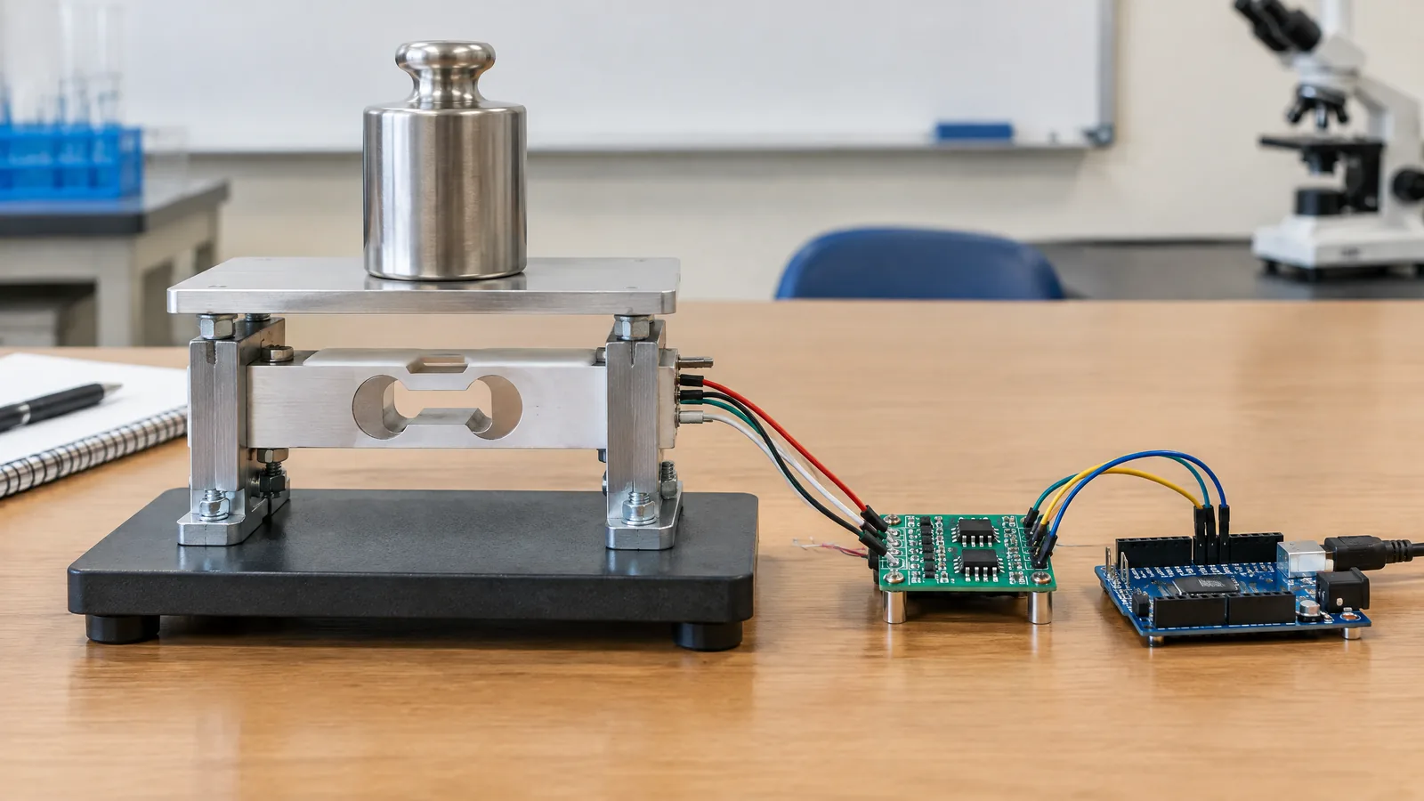
A motor can be spinning while the controller still does not know its shaft position, direction or speed. A magnetic rotary encoder solves that feedback problem by sensing a rotating magnetic target and producing electrical signals that a controller can decode into motion information; the sensor IC, magnet or ferrous target, mechanical alignment and decoding electronics work as one system.
This article is part of the computer hardware technology guide library.
Key takeaways
A magnetic rotary encoder uses magnetic sensing to turn rotary movement into position, speed or direction feedback. It is a complete sensing arrangement, not just a loose Hall-effect IC.
Two phase-shifted outputs, often called quadrature channels A and B, can let a controller count movement and infer direction when the target and sensor are designed for that output.
Air gap, magnet or target geometry, alignment, electrical noise and controller-side decoding affect the result. A datasheet number for one part is not a universal promise for every encoder.
Incremental feedback reports change from a reference, while an absolute encoder reports a coded position value. Choose the type according to what the system must know after movement or power loss.
- Use a magnetic rotary encoder when non-contact rotary feedback suits the mechanism.
- Treat the target, sensor placement and signal interface as a single design.
- Do not assume a motor controller can use the output without compatible decoding inputs.
What is a magnetic rotary encoder?
A magnetic rotary encoder is a position-feedback system for a rotating shaft. It normally combines a magnetic field source or shaped ferrous target, one or more magnetic sensing elements, signal-conditioning electronics and an output interface. As the shaft turns, the changing field pattern produces pulses, phase-shifted channels, an angle-related signal or a coded position value.
The word encoder describes the conversion from mechanical movement into an electrical signal. Rockwell Automation’s encoder primer describes encoders as devices that provide position and/or velocity feedback to a controller, while rotary encoders are used for shaft angle, turn count or velocity. In a motor application, the controller uses that feedback to compare actual motion with the requested motion and adjust its control decisions.
This is different from using a magnet sensor as a simple end-stop. A single Hall switch can indicate that a magnet crossed a threshold, but a rotary encoder arrangement is designed to provide repeated movement information as the shaft rotates. The exact output depends on the model and the target design.
How magnetic feedback reaches a motor controller
The signal path has four practical parts: the rotating target, the magnetic sensing element, output conditioning and controller decoding. The target may be a permanent magnet attached to a shaft or a ferrous toothed wheel used with a sensor that has an integrated magnet. The sensor detects the field pattern, and its electronics turn that response into a digital transition, pulse train, analogue level or serial position value.
For a motor, the controller may count transitions to estimate speed, compare channel timing to determine direction, or use the feedback as part of a position loop. The encoder does not decide the complete motor-control strategy. A motor driver, controller, power stage and software or firmware still have separate jobs, and their electrical interfaces must be compatible.
Allegro’s motor-driving application note gives a concrete example of a magnetic encoder producing two quadrature outputs, named channel A and channel B, for controller feedback. Its design discussion also shows why a magnetic encoder is not selected by the IC name alone: target pitch, tooth shape, air gap, Hall-element spacing and alignment influence phase and duty cycle.
What quadrature signals tell you
Quadrature means two repeating digital signals are offset in phase. A controller watches which channel changes first. That sequence indicates one direction; the reverse sequence indicates the other. Counting transitions gives relative movement, and the rate of those transitions can be used to estimate rotational speed when the target geometry and counts per revolution are known.
Quadrature does not automatically provide a physical zero or absolute shaft angle. An incremental encoder usually reports movement relative to a reference, so a system may need a homing mark, index signal or another reference procedure after startup. Rockwell’s primer distinguishes incremental encoders, which produce pulses with movement and do not retain position through a power cycle, from absolute encoders, which provide a unique position value and retain position through a power cycle.
Resolution is also a system property. More teeth or magnetic poles can create more transitions, but the sensor must still resolve the field pattern at the intended speed and air gap. More counts are not useful if the target geometry causes missed, distorted or ambiguous transitions.
| Feedback type | What the controller receives | Main limitation to remember |
|---|---|---|
| Incremental quadrature | Relative movement and direction from two phase-shifted channels | A power cycle or lost count does not by itself reveal absolute position |
| Incremental with index | Relative counts plus a once-per-revolution reference event | The controller still needs a suitable startup or recovery strategy |
| Absolute magnetic encoder | A coded shaft-position value over its specified range | The interface, resolution and power-loss behaviour depend on the model |
Why the magnet, target and air gap matter
The physical arrangement controls the field that reaches the sensing element. A small change in air gap, an offset shaft, a tilted magnet or a target with unsuitable tooth spacing can change the timing and amplitude of the output. Nearby ferrous parts can also alter the field. These are not installation details to solve after the electronics are finished; they are part of the encoder design.
In its ATS605LSG application note, Allegro gives device-specific example requirements of 50% ±10% duty-cycle accuracy, 90° ±10° phase-shift accuracy and a 0.5–3.0 mm air-gap range. It also explains that phase separation changes with air gap and discusses how sensor twist can adjust the apparent spacing for a particular target. Those figures illustrate the level of mechanical interaction involved, not a specification for every magnetic rotary encoder.
For a real design, start with the selected device’s data sheet and application guidance. Record the target material, magnet orientation or tooth pattern, shaft runout, expected air gap, speed range, supply conditions and output interface. Then validate the complete assembly across its intended operating range. Do not infer accuracy from a bench test with a hand-turned magnet.
Magnetic rotary encoder applications
Motor feedback is the main application in this topic: a controller can use rotary feedback to monitor speed, direction and relative position in a DC or brushless-DC system. Similar arrangements can support a rotary knob, a small robot joint, a conveyor axis or a position-sensitive actuator, provided the chosen encoder’s resolution, speed, environmental rating and interface suit the mechanism.
The useful advantage is non-contact sensing between the sensing IC and the rotating magnetic element or target. That can simplify some mechanical arrangements, but it does not remove wear, bearing, alignment or contamination concerns from the whole machine. A magnetic encoder is not a substitute for a properly specified motor driver, current protection, mechanical guard or safety-rated feedback system where those are required.
For beginner electronics projects, an encoder breakout board may include the sensor, magnet and interface circuit. Treat that board as an optional convenience, not as a universal component. Some boards expose raw Hall outputs, while others include a decoder or microcontroller. Check the pinout, output voltage, pull-up requirement and whether the host board can count the signal reliably.
Limitations and selection checklist
A magnetic rotary encoder can report only what its sensing geometry and output format support. It may lose counts when the shaft turns too quickly for the input, report the wrong direction when channels are wired or decoded incorrectly, or show unstable transitions when the field is marginal. A sensor that works with a hand-turning knob may not meet the timing needs of a fast motor.
Before choosing one, answer five questions: Is relative or absolute position required? What speed and resolution must be measured? Is the target a magnet, a multipole ring or a ferrous wheel? What air gap and alignment can the mechanism hold? Which electrical interface can the controller decode? Then check temperature, supply, output current or pull-up needs, noise immunity and the manufacturer’s mounting guidance.
Keep the safety boundary clear. Feedback is an input to a control system, not proof that a motor is safe to touch or that a robot joint cannot move unexpectedly. For powered machinery, use the protections and engineering review required by the application rather than relying on an educational encoder project.
- Define the required position information: incremental, indexed or absolute.
- Match counts or resolution and maximum input frequency to the shaft speed.
- Design the magnet or target, air gap and alignment from the selected device documentation.
- Confirm the controller can decode the output voltage, timing and interface.
- Test the finished mechanical and electrical assembly, not only the sensor on a loose bench.
Magnetic rotary encoder FAQs
These answers describe the general sensor arrangement. The selected part’s data sheet remains the authority for electrical limits, resolution, speed and mounting details.
Can a magnetic rotary encoder measure motor speed?
Yes. A controller can derive speed from the rate of encoder transitions when it knows the target geometry and counts per revolution. The encoder’s maximum input frequency and the controller’s counting method still limit the usable range.
Is a magnetic rotary encoder the same as a Hall sensor?
Not exactly. Hall sensing may be the physical technology inside an encoder, but a rotary encoder also includes the target arrangement, output timing and controller interpretation needed to report shaft movement. A single Hall switch is not automatically a rotary encoder.
What is quadrature in a rotary encoder?
Quadrature uses two periodic outputs that are shifted in phase. The controller uses their order to infer direction and their transitions to count relative movement. It does not by itself establish absolute shaft position after power loss.
Can I connect any magnetic encoder to an Arduino or motor driver?
No. Check the encoder’s supply and output levels, pull-up or line-driver requirements, maximum transition rate and signal format. Also check whether the Arduino or motor driver has an input designed to decode that output; a raw sensor signal may need conditioning or firmware decoding.
Why does encoder air gap matter?
Air gap changes the magnetic field seen by the sensing elements. It can affect switching timing, phase separation and whether the signal remains strong enough for reliable decoding. The acceptable range is part-specific and must be maintained by the mechanical design.
About the image
AI-generated editorial illustration; not an actual product or mission photograph.
Source notes
Reporting record
techduopulse stores source destinations privately. Public notes remain non-clickable so every visitor journey stays on this website.
Source note: Allegro MicroSystems magnetic encoder motor-driving application note
Primary source · Hall magnetic encoder feedback, quadrature outputs, target geometry, air gap, phase and duty-cycle designSource note: Rockwell Automation motion-systems encoder primer
Secondary source · Encoder feedback, rotary use, incremental versus absolute behaviour and controller signalsNew distinct application article for magnetic rotary encoder motor control. It extends the site’s broad magnetic and Hall coverage into the encoder signal chain, quadrature decoding, incremental-versus-absolute feedback, target geometry, air-gap limits and controller compatibility. Device-specific Allegro values are explicitly qualified and no unsupported tests, rankings, statistics or safety-critical build instructions are included.