SEO title: Hall Effect Sensor: Working Principle Explained Meta description: Learn what a Hall effect sensor is, how Hall voltage detects magnetic fields, and how analog, digital, and Arduino uses work in India.
This article is part of the software engineering technologies guide library.
What is a Hall effect sensor?
A Hall effect sensor is an electronic component that responds to magnetic flux near its active area. Inside, a small semiconductor element carries a bias current. When a magnetic field crosses that current in the appropriate direction, charge is pushed sideways and a transverse voltage appears. This is the Hall voltage. With no significant magnetic field, the voltage is negligible. The phenomenon was discovered by Edwin Hall in 1879. [1]
The sensor does not “see” every magnet in the same way. Magnetic-field strength, polarity and orientation all matter. A magnet that works when presented to one face of an IC may not work when rotated or moved farther away. The package drawing and magnetic characteristics in the device datasheet identify the sensitive axis and the conditions the device is designed for. [1]
Hall effect sensor working principle
The raw Hall voltage is very small, so a Hall-effect IC contains electronics that make the signal useful. The result depends on the sensor family.
A linear or analog Hall IC conditions the Hall signal and produces an output that changes approximately in proportion to magnetic flux density across its specified linear range. This can help a circuit observe a changing magnetic field rather than make only a yes/no decision. [1] [2]
A digital Hall sensor acts more like a magnetic switch. It changes output state when the field reaches its operate point, often written as BOP, and returns when the field falls to its release point, BRP. The difference between those thresholds is hysteresis. It helps prevent rapid, unwanted switching when the field is close to a threshold or noisy. [1] [2]
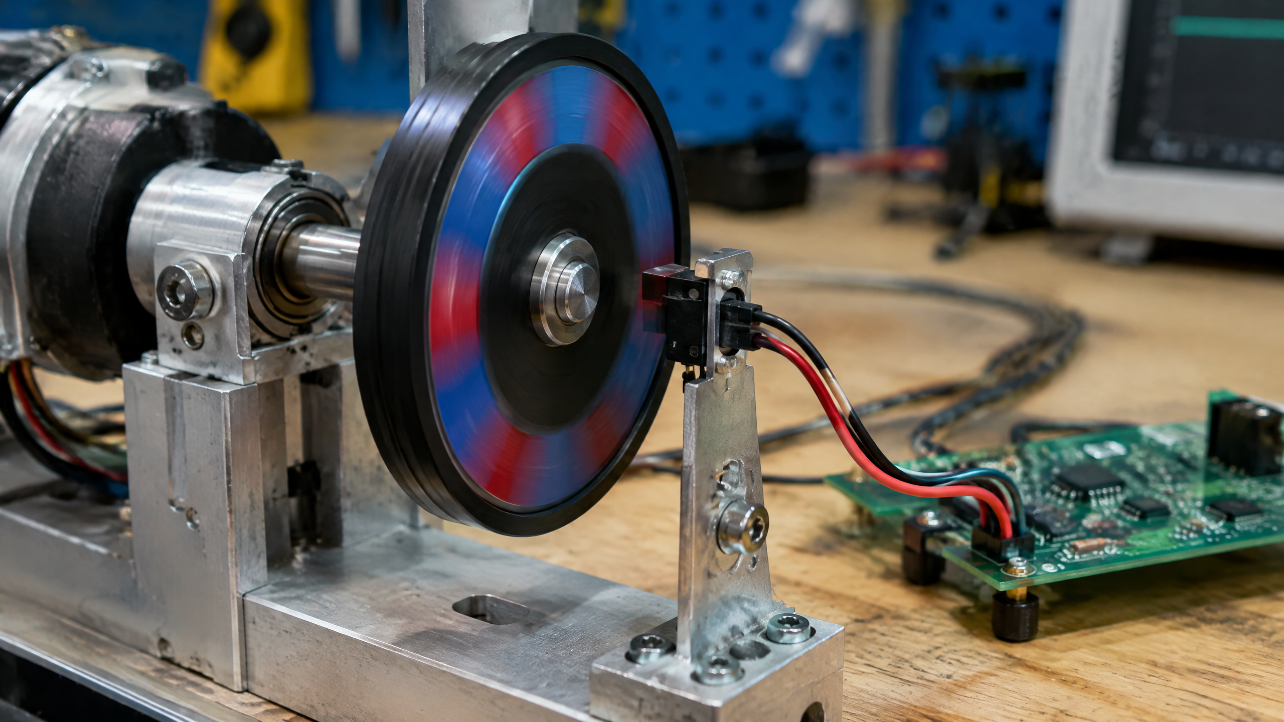
In a rotating-wheel setup, for example, a magnet or suitable magnetic target passes the sensor. Each valid field change can become a pulse for a controller. The controller can then use the pulse pattern as one input for position or speed sensing. Whether it works in a real design still depends on the magnet or target geometry, distance, sensor orientation and the particular IC’s limits.
Main Hall effect sensor types
| Type | What the output represents | Typical use context | What to check |
|---|---|---|---|
| Analog / linear Hall sensor | A changing analogue signal over a specified field range | Measuring changing field level, position or current-related magnetic field | Sensitivity, linear range, offset, temperature behaviour and signal conditioning |
| Digital Hall switch | An on/off state after a magnetic threshold is crossed | Proximity, rotation, gear motion and commutation | Operate/release points, hysteresis, output type, polarity and pull-up requirement |
Digital sensors have further variations. A unipolar device responds to one magnetic polarity. An omnipolar device can respond to either polarity. Do not assume that any magnet will trigger any Hall IC: the sensing rule comes from the part’s datasheet. [2]
Output circuitry also differs. Some digital devices have an open-drain or open-collector output, which commonly needs an appropriate pull-up arrangement. Others use a push-pull output. Connecting a module to a microcontroller without checking its supply and output design can lead to an unreadable signal or electrical incompatibility. [1] [2]
Hall effect sensor applications
Hall ICs are used for contactless position, proximity, rotation and speed sensing, as well as gear motion, current sensing and brushless-DC (BLDC) motor commutation. [1] [3] In practice, the sensor is only one part of the system. The magnet or target, mechanical alignment, electronics and environment all affect the outcome.
Common examples include:
A rotating shaft or wheel can bring a magnet past a digital Hall switch to create pulses.
A movable cover or mechanism can use a magnet and sensor for a non-contact position indication.
BLDC motor systems can use Hall sensing to provide rotor-position information for commutation.
A current-carrying conductor creates a magnetic field that a suitably designed Hall-based system can use for current measurement.
These uses are familiar in Indian engineering labs, embedded projects, appliances, vehicles and industrial equipment. They are examples of sensing patterns, not proof that a generic sensor module is suitable for a specific machine, vehicle or protective function.
Hall effect sensor Arduino: a careful starting point
A Hall effect sensor Arduino project can be a useful way to learn about digital inputs, pulses and magnetic fields. Before writing code, identify whether the board has a digital switch output, an analogue output, or both. Then confirm its supply range, output stage, pin labels and the polarity that triggers it.
For a basic digital experiment, a microcontroller reads a change in the sensor output while a magnet is brought near the specified sensing face. A sketch can count valid transitions or report the present state. For an analogue device, the program must read a varying voltage and interpret it only within the device’s stated operating range. Neither approach produces a universal distance reading: magnet strength, spacing, alignment, supply conditions and the specific sensor determine the response. [1] [2]
Use a datasheet and a known, compatible board arrangement rather than copying a wiring diagram for a differently labelled module. If the project will control movement, high power or a safety-related function, treat a hobby demonstration as a learning step—not as a validated design.
Accuracy, calibration and practical limits
It is tempting to treat a Hall sensor as a simple “magnet detected” device. Real measurements are more conditional. A digital IC’s actual thresholds can vary with manufacturing process, supply voltage and temperature. The magnet must create sufficient field at the sensor to guarantee a switching condition. [2]
For analogue sensing, sensitivity, linear range, offset and temperature behaviour are part-specific. For digital sensing, BOP, BRP, hysteresis, output configuration and polarity are especially important. In either case, magnet-to-sensor distance and field orientation are not minor setup details; they are part of the measurement system. [1] [2]
Calibration or system testing may be appropriate when the application needs a meaningful position, speed or current value. A practical check can include the intended magnet or target, full movement range, expected supply conditions and realistic temperatures. This does not turn a sensor into a guaranteed measurement instrument, but it can reveal whether the chosen arrangement behaves as expected.
Reading a Hall sensor datasheet
Before choosing a circuit or interpreting a result, look for these terms:
Sensitive axis or active face: the field direction and package area that matter.
BOP and BRP: the operate and release thresholds for a digital switch.
Hysteresis: the gap between BOP and BRP that helps avoid unstable switching near a threshold.
Polarity: whether the part is unipolar or omnipolar.
Sensitivity and linear range: key analogue specifications, where applicable.
Supply and output type: especially whether the output is open-drain/open-collector or push-pull.
Those details explain why two parts both called “Hall effect sensors” may behave very differently. They also help an Arduino learner decide whether a pull-up, analogue input or different logic arrangement is needed.
Frequently asked questions
Hall effect sensor kya hai?
A Hall effect sensor is a component that converts a magnetic field near its active area into an electrical signal. Depending on the device, that signal may be an on/off output or a changing analogue output. [1] [2]
What is a Hall effect sensor in Hindi?
In plain Hindi, it can be described as a magnetic field ko electrical signal mein badalne wala sensor. The important technical detail is that it responds to field strength, direction and, for some parts, polarity—not simply to the presence of any magnet.
What is the Hall effect sensor working principle?
A current flows through a semiconductor element. A magnetic field crossing it in the appropriate orientation produces a sideways Hall voltage. Integrated electronics amplify or process that small effect into an analogue output or a digital switching signal. [1] [2]
What are the main Hall effect sensor types?
The main practical groups are analogue/linear Hall sensors and digital Hall switches. Digital parts can also be unipolar or omnipolar, and their output circuits may differ. Always use the individual datasheet to identify the type. [2]
How does a Hall effect sensor Arduino module work?
A module typically puts a Hall IC on a small board and may add supporting circuitry. The Arduino reads the module’s documented output, but the wiring and code depend on whether that output is analogue or digital and on the board’s supply and output design. Check the module and IC documentation before connecting it.
Can I use Hall effect sensor connection and code from any tutorial?
Not safely as a universal template. Pin labels, voltage limits, output style, magnetic polarity and trigger thresholds differ between modules and ICs. Start from the documentation for the exact part and verify the circuit with a low-risk test setup.
What are Hall effect sensor applications in India?
The same core applications apply in India as elsewhere: contactless position and proximity sensing, rotating-speed or gear-motion detection, current-related magnetic measurement and BLDC motor commutation. The suitable sensor and installation still depend on the equipment’s requirements and conditions. [1] [3]
Related reading
/article/magnetic-sensor-explained
/article/proximity-sensor-types-working
/article/accelerometer-explained
/article/pressure-sensor-working-principle-types
Source notes
Reporting record
techduopulse stores source destinations privately. Public notes remain non-clickable so every visitor journey stays on this website.
https://support.google.com/trends/answer/4365533?hl=en
Primary source · Research source 4https://developers.google.com/search/docs/monitor-debug/trends-start
Primary source · Research source 5https://www.allegromicro.com/en/insights-and-innovations/technical-documents/hall-effect-sensor-ic-publications/hall-effect-ic-applications-guide
Primary source · Research source 1https://www.ti.com/lit/slia086
Primary source · Research source 2https://www.lakeshore.com/products/categories/magnetic-products/hall-(magnetic
Primary source · Research source 3New India-focused sensor explainer covering Hall effect sensor, working principles, uses and limitations.