A motor controller or solar project can show a current value that looks plausible while the sensor range, conductor position or ADC scaling is wrong. A Hall-effect current sensor measures the magnetic field produced by current in a primary conductor and turns it into a conditioned analogue signal, allowing a suitably designed microcontroller system to observe DC current with galvanic isolation provided by the rated sensor design.
This article is part of the computer hardware technology guide library.
Key takeaways
A Hall-effect current sensor is a current-sensing IC or module designed around a primary current path; it is not the same thing as a generic Hall switch.
The measured conductor and the Hall element are separated in the sensor’s magnetic structure, but the actual isolation rating, creepage, clearance and PCB layout remain part-specific design requirements.
The output is commonly an analogue voltage that an MCU ADC can read. Range, offset, sensitivity, bandwidth, temperature behaviour and calibration determine whether that reading is useful.
A shunt resistor can be a better fit for some low-side or precision designs. Compare isolation, heat, common-mode voltage, bandwidth and accuracy instead of choosing by name alone.
- Use the exact sensor datasheet and its specified current path.
- Treat the ADC reading as a scaled signal that needs correct reference, filtering and calibration.
- Do not use a hobby module as a substitute for a rated power or safety design.
What does a Hall-effect current sensor measure?
A Hall-effect current sensor measures current indirectly. Current flowing through the sensor’s primary conductor creates a magnetic field. A Hall element detects the field and internal signal conditioning produces an electrical output related to the current. Texas Instruments describes this class as an inherently isolated current-sensing approach in which an MCU ADC can read a proportional analogue voltage.
The physical parts have different jobs. The primary path carries the measured current, the magnetic structure guides or concentrates its field, the Hall element detects that field, and the signal electronics provide the output. A microcontroller, ADC input, filter or monitoring software is external to the physical sensor. Some modules add a board, connector, supply decoupling or filtering, but those additions do not change the ratings of the IC inside.
This is why a generic Hall switch cannot automatically replace a current sensor. A switch is normally designed to change state at a magnetic threshold. A current-sensor IC is designed around a specified current path, field conversion, output range and electrical isolation structure.
How a Hall-effect current sensor circuit connects to an MCU
The basic signal path is simple: the DC bus, motor lead or solar-current conductor passes through the rated primary path; the sensor is powered on its low-voltage side; and its analogue output goes to an MCU ADC input. Firmware then converts the ADC code into a current estimate using the sensor’s documented zero-current output and sensitivity. The exact equation, polarity and reference voltage depend on the chosen part.
At zero current, an analogue Hall output may sit at a defined quiescent level rather than at zero volts. Positive and negative current can move the signal in different directions on a bipolar device, while a unidirectional device may be intended for one current direction. Check the output range before connecting it to a 3.3 V or 5 V ADC; a voltage outside the ADC’s permitted input range can make the measurement invalid or damage the input.
A decoupling capacitor, an RC filter, a separate ADC reference or a signal buffer may be recommended by the device documentation. These are optional or model-specific external components, not universal requirements. The sensor’s bandwidth should also match the job: a slow battery monitor, motor-current feedback loop and switching-transient measurement do not ask for the same response.
- Identify the exact sensor, current direction convention, supply range and analogue-output limits.
- Route only the intended primary current through the rated current path and keep the low-voltage side within its documented domain.
- Connect the output to a compatible ADC input with the recommended decoupling and filtering.
- Convert ADC readings using the stated zero-current level and sensitivity, then validate the result against a suitable reference before relying on it.
Isolation, layout and current range are part of the measurement
The word isolated does not mean that every installation is automatically safe. Isolation performance belongs to the exact package and system design. Check the rated working and transient voltages, creepage and clearance, insulation construction, PCB spacing, connector arrangement and applicable standards. Do not infer a high-voltage rating from a low-cost board’s marketing label.
Current range matters just as much. A sensor can saturate when the primary current exceeds its specified range, while a very small current may be difficult to resolve once offset, noise and ADC limitations are included. The conductor’s position and nearby magnetic materials also influence the field seen by the Hall element. Allegro’s applications guide notes that field around a conductor decreases with distance; the mechanical current path is therefore part of the sensor arrangement, not an afterthought.
Temperature can shift offset and sensitivity. Switching supplies and motor drives can add fast changes or noise. TI’s data-sheet guidance recommends examining sensitivity, linear range, linearity, noise, supply conditions and temperature rather than treating the output as an ideal voltage. Use the limits from the selected part, not values remembered from another Hall sensor.
| Design question | What to check | Why it matters |
|---|---|---|
| Can the sensor carry the current? | Continuous, peak and bidirectional current ratings for the primary path | Over-range current can heat the path or saturate the magnetic measurement |
| Can the MCU read the output? | Supply, quiescent output, sensitivity, output swing and ADC input limit | A correct current can still produce a wrong code if scaling or range is mismatched |
| Is the isolation suitable? | Working voltage, transient rating, creepage, clearance and package data | Isolation is a rated construction and layout requirement, not a generic Hall feature |
| Will the signal be fast enough? | Bandwidth, response time, noise and filter behaviour | Filtering that helps a battery reading may hide useful motor or converter changes |
Hall-effect current sensor vs shunt resistor
A shunt resistor measures current from the small voltage developed across a known resistance. It can offer a direct, precise signal, but it dissipates power and may require an amplifier or isolated front end when the measured conductor is at a high common-mode voltage. A Hall-effect current sensor measures through magnetic coupling and can provide isolation in the sensor structure, avoiding a direct resistive element in the signal path.
Neither approach wins every design. A Hall sensor may add offset, magnetic and temperature errors, and the sensor’s bandwidth and current range must fit the application. A shunt may be attractive where heat is acceptable and the voltage domain is manageable. Compare the full signal chain: isolation, loss, thermal drift, common-mode voltage, response, calibration effort, board layout and required protection.
Common mistakes when reading the ADC
The most common mistake is assuming that ADC code equals current without first finding the zero-current output and sensitivity in the datasheet. Also check whether the part is bidirectional, whether its output is ratiometric to supply, and whether the ADC reference uses the same supply. A changing supply can otherwise appear as changing current.
Another mistake is calibrating only one convenient operating point. Offset can change with temperature and installation, while the conductor and nearby metal can alter the magnetic field. If the application needs a meaningful current value, validate the complete installed arrangement across its intended range and conditions using an appropriate reference instrument. Do not claim accuracy from a short LED or serial-monitor demonstration.
Finally, do not place a sensor board into a high-energy DC bus merely because its pins fit. Confirm fusing, insulation, enclosure, connector spacing and the limits of every connected instrument. A learning circuit is not a validated power-control or protective system.
Frequently asked questions
These answers apply to Hall-effect current-sensing ICs as a class. The exact datasheet remains the authority for a selected model or module.
Can a Hall-effect current sensor measure DC current?
Yes. Hall-effect current sensors can detect the magnetic field from a DC current, and application guides describe current-sensing response from DC into the kHz region. The useful range and response still depend on the exact device, conductor arrangement and specified bandwidth.
Does a Hall-effect current sensor provide isolation?
Many dedicated Hall-effect current sensors use an isolated magnetic sensing structure, but the useful isolation rating is part-specific. Check working voltage, transient rating, creepage, clearance, package construction and PCB layout before connecting it to a high-voltage bus.
Can I connect its output directly to an Arduino or other MCU?
Only after checking the sensor supply, output range, polarity, quiescent level and the MCU ADC’s input limits. A compatible ADC connection may be possible, but wiring and scaling are not universal across sensors or modules.
Is a Hall current sensor better than a shunt resistor?
Not universally. Hall sensing can simplify isolated measurement and avoid the normal shunt voltage drop, while a shunt can offer a direct low-voltage signal and strong precision in a suitable domain. Choose after comparing isolation, heat, common-mode voltage, bandwidth, range and calibration.
Why is my Hall current reading wrong at zero current?
The output may have a deliberate quiescent offset, and the measured arrangement may add sensor offset, supply variation, temperature drift, noise or magnetic interference. Confirm the documented zero-current output and recalibrate only within the method and conditions supported by the selected device.
About the image
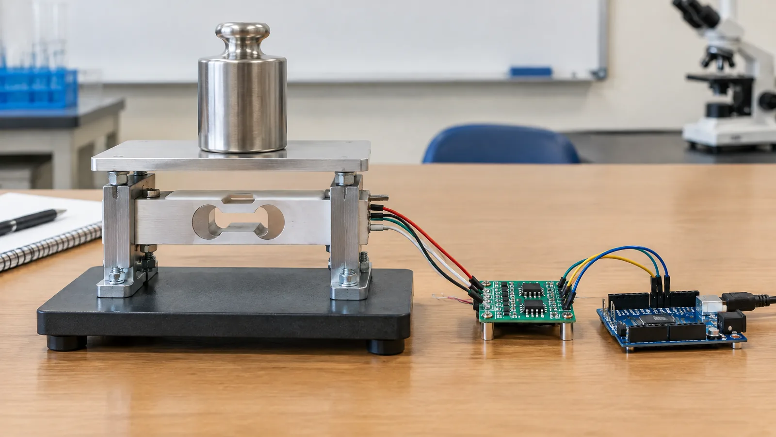
AI-generated editorial illustration; not an actual product or mission photograph.
Source notes
Reporting record
techduopulse stores source destinations privately. Public notes remain non-clickable so every visitor journey stays on this website.
Source note: Texas Instruments current-sensing solutions overview
Primary source · Hall-effect current sensing, inherent isolation, proportional analogue output, MCU ADC path and technology comparisonSource note: Texas Instruments Hall-effect sensor data-sheet application note
Primary source · Magnetic flux, analogue output, sensitivity, linear range, polarity, noise and data-sheet interpretationSource note: Allegro MicroSystems Hall-effect sensors applications guide
Primary source · Current limiting and measurement, DC-to-kHz response, conductor field geometry and current-sensor IC applicationsNew distinct application page for the Hall-effect current sensor circuit query. Separates a dedicated current-sensing IC/module from the existing broad Hall-effect guide, explains the primary current path and MCU ADC signal chain, qualifies isolation and layout requirements, compares Hall sensing with shunts, and avoids universal ratings or unverified test claims.