
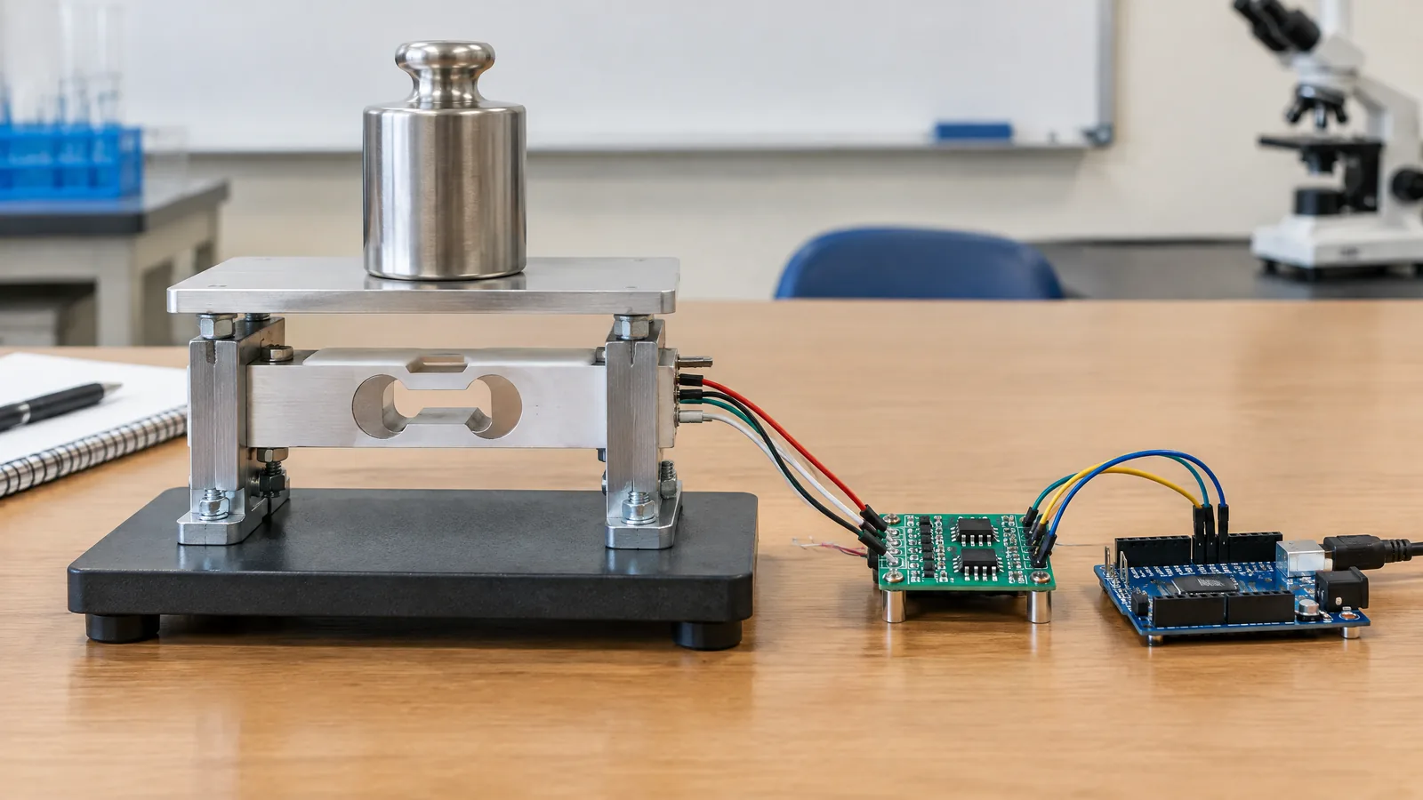
When a load cell HX711 Arduino scale shows a changing number after you place a box on it, the number is only useful if the load reaches the sensor in a repeatable way. A strain-gauge load cell with HX711 lets a beginner turn that force response into a readable weight estimate, but the HX711 is the bridge amplifier and ADC interface—not the physical sensor—and the assembled setup still needs calibration.
This article is part of the computer hardware technology guide library.
Key takeaways
A load cell senses strain in a designed metal body; the HX711 reads its very small bridge signal so a microcontroller can process it.
The reading is a property of the whole measurement chain: platform, force path, load cell, wiring, HX711, code and calibration.
Use a known load under the final mounting arrangement to set the scale factor, then recheck when the fixture or environment changes.
Keep this as a learning or low-consequence measurement project. It is not approval for trade-by-weight, medical, lifting or safety decisions.
What each part does in a load cell HX711 Arduino setup
The physical load cell is the force sensor. In a strain-gauge design, a small elastic deformation changes the resistance of bonded gauges arranged as a Wheatstone bridge. A weighing platform transfers the load into the cell’s intended force path. The cell does not directly output a ready-made kilogram value; it produces a small electrical change related to applied force.
The HX711 breakout is optional signal-conditioning and conversion hardware for this project. It supplies the bridge interface and turns the small differential signal into data a controller can read. An Arduino-compatible board then runs the program that tares the empty platform, applies a calibration factor and displays or records the result. A platform, spacers, fasteners, enclosure, display and power supply are project components, not part of the sensor itself.
Do not assume that a module name guarantees compatibility. Check the exact load-cell datasheet and HX711 board documentation for bridge arrangement, excitation, pin labels, supply and logic levels. SparkFun notes that typical wire colours can vary, so identify E+/E− and signal connections from the documentation rather than copying a colour chart blindly.
How the measurement chain becomes a scale reading
A useful mental model is: load enters the platform, the cell flexes slightly within its intended range, the bridge output changes, the HX711 samples that change, and the Arduino converts the readings into a displayed estimate. Gravity makes a placed object exert force; the software label may say grams or kilograms, but that label is meaningful only after the setup has been related to a known load.
The HX711 board commonly exposes the load-cell bridge connections and digital DAT and CLK lines to the microcontroller. SparkFun describes separate analogue and digital supply roles on its breakout, so follow the board’s documented voltage arrangement—especially when the controller uses 3.3 V logic. GPIO pin choices can be changed in code, but that does not remove the need to wire the correct functions.
If the number moves in the opposite direction from the one you expect, the bridge signal polarity may be reversed; SparkFun’s guide describes reversing the two output signal wires as a way to reverse reading direction. That is a wiring interpretation, not a correction for bad mounting or an overloaded cell.
A safe calibration workflow for a learning scale
Calibration should happen after the platform, cell, wiring and code are in the arrangement in which they will be used. First allow the empty platform to settle and record a zero or tare value. Then place a suitable known load centrally and let the reading settle. Adjust the scale factor so the displayed result corresponds to that known load, remove it, and repeat the check. SparkFun’s example follows this same practical pattern: tare with no weight, apply a known weight and adjust the calibration factor for the particular setup.
Use a known load that is appropriate for the exact cell and fixture. Do not treat a random household object as a certified standard, and do not copy a calibration factor from someone else’s project. A factor can change with the cell, orientation, platform, unit choice and signal direction. If you change the platform, fasteners, load point or software averaging, calibrate again.
A useful beginner check is to place the same known load more than once and at more than one reasonable position on the platform. A large difference suggests a mechanical or installation problem, not simply a number to hide in software. Record the conditions and stop if the cell bends permanently, the platform rocks, wiring becomes hot, or the readings remain unstable.
- Check the part documentation and build the intended load path.
- Power the interface as its documentation specifies and confirm the empty-platform reading.
- Tare with no load, then apply a known load without exceeding the documented range.
- Adjust the project’s calibration factor until the unit and known load agree.
- Remove and replace the load to check repeatability before using the scale for an experiment.
Why readings drift or disagree
Mounting is part of the instrument. Side loading, off-centre force, a flexible platform, friction against the enclosure or a fastener that touches the wrong surface can divert force around the sensing element. TE Connectivity lists overloading, side loading and poor mounting among causes of distorted readings. Keep the intended force direction clear and never use a cell outside its documented loading arrangement.
Electrical and environmental conditions matter too. Noise, cable resistance, unstable excitation, temperature changes, humidity and electromagnetic interference can affect the result. Shielding, tidy wiring, a stable supply and sensible software averaging may help, but filtering cannot repair a poor force path. A reading that looks repeatable on a desk is not automatically accurate after the fixture, temperature or load position changes.
Strain-gauge systems can also show non-linearity, hysteresis, zero shifts, creep or longer-term drift. Re-tare or recalibrate only after finding the likely cause; changing the calibration factor can mask a mechanical fault. For a class, feeder or stock-bin experiment, describe the result as an estimate and state the conditions under which it was calibrated.
Where this project fits—and where it does not
This combination is useful for a classroom demonstration, a small stock-bin monitor, a feeder experiment or a simple data-logging exercise where the goal is to learn how physical force becomes digital data. It can teach bridge circuits, ADC readings, units, repeatability and the difference between a sensor and its interface.
It should not be presented as a certified weighing instrument or used by itself for billing, medicine, lifting protection, vehicle loading, building safety or any decision where a wrong measurement could injure someone or create a legal or financial problem. For those contexts, use equipment and calibration procedures intended for that application.
The most honest result is not a promise of a universal accuracy figure. It is a documented setup with a specified load range, a known calibration method, repeatability checks and clear limits.
Load cell HX711 Arduino FAQs
The most common beginner questions are about component roles and calibration, so keep the answers tied to the actual assembled project.
Is the HX711 the load cell?
No. The load cell is the physical strain-gauge force sensor. The HX711 is an interface chip or breakout used to excite/read the bridge and provide data to a microcontroller.
Can I connect a load cell directly to Arduino?
A bridge load cell produces a very small signal, so a suitable amplifier and ADC interface such as an HX711-style board is normally used. Follow the exact board and load-cell documentation rather than assuming a universal pinout.
How do I calibrate a load cell with HX711?
Assemble the final platform, tare it empty, place a suitable known load, and adjust the project’s calibration factor until the displayed unit matches that known load. Repeat the check after changing the mechanics or wiring.
Why does my scale reading change when I move the object?
The load path may be changing because of off-centre loading, platform flex, friction or poor mounting. Recheck the fixture and intended loading direction before trying to correct the result in software.
Can this Arduino scale be used for trade or safety decisions?
No. A hobby or classroom setup is not automatically certified or suitable for trade-by-weight, medical, lifting, vehicle, building-safety or other high-consequence use.
About the image
AI-generated editorial illustration; not an actual product or mission photograph.
Source notes
Reporting record
techduopulse stores source destinations privately. Public notes remain non-clickable so every visitor journey stays on this website.
Source note: TE Connectivity load-cell fundamentals and calibration guidance
Primary source · Sources of error, mounting, calibration, drift and environmental limitationsSource note: SparkFun HX711 breakout hookup and calibration guide
Secondary source · Bridge/interface roles, supply and signal connections, wire-colour caution and known-load calibration exampleRelated reading: techduopulse force-sensor guide
Context source · Existing broad guide reviewed to avoid duplication; related internal context onlyNew application tutorial created from the supplied brief and two fetched technical sources. It separates the physical strain-gauge load cell from the HX711 interface, explains the complete Arduino measurement chain, gives a known-load calibration workflow, and qualifies mounting, drift, environmental and high-consequence-use limitations without asserting product-specific accuracy or pinouts.


