When a rocket test team needs to know how much liquid passed from a run tank during a stable test interval, a simple full-tank percentage is not enough. A propellant liquid-level gauge / magnetic float switch is a rocket propellant level sensor that can mark discrete liquid-level points, letting the facility compare a tank-volume change with flowmeter pulses; it is a ground-test instrument example, not a universal sensor fitted to every flight tank.
This article is part of the emerging technology science guide library.
What a rocket propellant level sensor measures
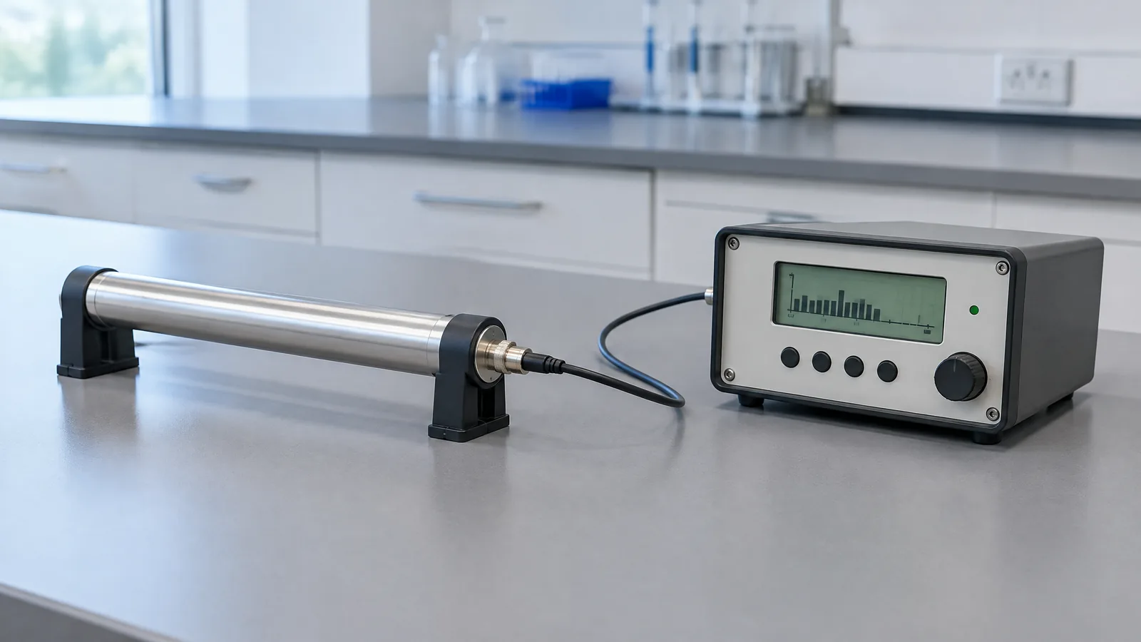
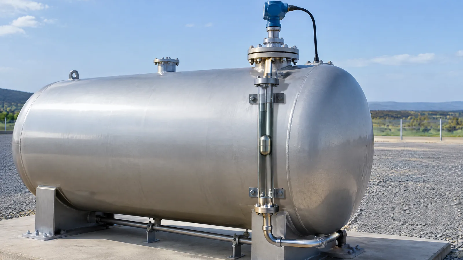
In the NASA Stennis example, the sensor is best understood as a liquid-level gauge and switch assembly. A float moves with the liquid, a magnet moves with the float, and magnetic reed switches inside a carrier tube change state as the float passes their positions. The result is a series of level thresholds rather than a continuously reported height. [1]
That distinction matters. A point-level switch can answer questions such as whether the liquid has reached one of several marked positions. A continuous level transmitter instead reports a changing value across a range. The Stennis presentation documents the first type in a facility flowmeter-calibration arrangement; it does not establish that every launch vehicle tank uses it or that the assembly alone provides continuous propellant mass. [1]
The physical float, magnet, reed switches and carrier tube are the sensing assembly. The wiring, discrete input channels, time stamps and data-reduction software are supporting instrumentation. A gauge reading is therefore one part of a measurement chain, not a complete accounting result by itself.
- Float assembly: follows the liquid surface or level movement.
- Magnet: travels with the float and actuates switches without requiring the switch contacts to sit in the liquid.
- Magnetic reed switches: provide separate open/closed or on/off threshold states.
- Acquisition and data reduction: record switch changes and relate them to flowmeter pulses and elapsed time.
How the magnetic float gauge supports ground-test accounting
NASA Stennis describes an in-place calibration method for facility flowmeters during rocket-engine ground-test hot-fire runs. The reason is practical: the facility handles very large flow rates, so removing a flowmeter or recreating the same conditions elsewhere can be difficult. The tank-level switch intervals provide a way to calculate how much volume changed while the flowmeter produced its pulse signal. [1]
The arrangement includes a cylindrical run tank, the float-and-magnet switch gauge, a flowmeter and calibrated volumetric standards. In a separate water-calibration step, water flows through the flowmeter into a precisely measured, NIST-traceable standard. The resulting tank-volume relationship is then corrected for the cryogenic-propellant situation, including the presentation's stated tank-shrinkage consideration between ambient and propellant temperatures. [1]
During a suitable test interval, the system records the beginning and ending switch states and the flowmeter pulses over the same period. The tank-volume change divided by elapsed time gives a derived volumetric flow rate. The flowmeter pulse rate is then compared with that derived rate to calculate a flowmeter constant. This is why a discrete gauge can be useful even though it does not produce a new level value at every instant. [1]
| Measurement element | What it contributes | What it does not establish by itself |
|---|---|---|
| Magnetic float switch gauge | Marks defined tank-level or tank-volume intervals | A continuous height, density-compensated mass, or flight-wide standard |
| Flowmeter pickup and acquisition channel | Counts pulses over the same interval | The tank volume without a calibrated level-to-volume relationship |
| Calibration and data reduction | Combines interval volume, time, pulses and corrections | A claim that the raw switch state is an independent mass measurement |
Discrete level switching versus continuous propellant sensing
A rocket liquid level gauge may be called a level sensor even when its useful output is a set of discrete transitions. That output is suitable for interval-based accounting when the tank geometry, switch locations and calibration records are known. It should not be described as a continuous transducer unless the source documents continuous output and the required conversion method. [1]
NASA's separate Fiber Optic Sensing System (FOSS) presentation shows why the distinction is useful. FOSS was developed around optical measurements and NASA described launch-system research involving liquid-level measurement and cryogenic propellant mass-gauging or stratification work. That is an external, optical sensing path under development and application study, not the same component as the Stennis magnetic float and reed-switch assembly. [2]
In other words, a float switch can provide robust threshold events while an optical or other model-specific system may be investigated for continuous, distributed or mass-related information. The words “propellant level sensor” do not identify one universal hardware design. The medium, tank geometry, temperature, pressure, desired output and qualification context all change the engineering choice.
- Use “discrete level gauge” or “magnetic float switch” for the Stennis-style threshold assembly.
- Use “continuous level” or “mass gauging” only when the documented instrument and conversion method support that output.
- Treat optical fibre sensing, pressure-based sensing and other external instruments as separate architectures, not interchangeable names for the float switch.
Limits of the ground-test example
The NASA source is a facility presentation, so its example should be read within that scope. It documents a ground-test flowmeter-calibration and tank-volume accounting method. It does not say that all propellant tanks on operational launch vehicles use a magnetic float switch, nor does it provide a general performance rating for every float gauge. [1]
The calculated result depends on more than the switch changing state. The facility needs a known relationship between switch intervals and tank volume, a calibrated reference volume, synchronized flowmeter data and corrections appropriate to the test condition. Transfers, power changes, transient periods or other test-system changes can make an interval unsuitable for the specific procedure described by NASA. Those are source-specific procedure boundaries, not a recipe for building or operating a propulsion system. [1]
This sensor class also should not be presented as a stand-alone safety control. A reader evaluating a real cryogenic or propellant installation must use the responsible facility's approved design, hazard analysis, qualification, instrumentation and control procedures. The useful lesson for beginners is narrower: understand what the physical sensor outputs before interpreting a tank-level number or a flow-accounting result.
Key takeaways
A magnetic float switch is a discrete rocket propellant level sensor: its reed switches mark level thresholds as a float and magnet move.
In NASA Stennis' ground-test example, switch intervals help derive tank-volume change for in-place facility flowmeter calibration.
The calibration result combines the gauge with tank-volume calibration, flowmeter pulses, timing and test-condition corrections.
A continuous optical or mass-gauging system is a different architecture; do not describe the float switch as a universal flight-tank sensor.
Frequently asked questions
These answers refer to the documented NASA ground-test example and keep its facility scope separate from general launch-vehicle claims.
Is a rocket propellant level sensor always a continuous sensor?
No. The NASA Stennis example uses a float assembly with a magnet and internal magnetic switches to create discrete level or volume-interval events. A continuous level or mass measurement needs a different documented output and conversion method.
How does a magnetic float switch work in a propellant tank?
A float follows liquid-level movement. A magnet attached to or carried by the float passes magnetic reed switches positioned in a carrier tube, changing their open/closed states at defined positions. The switches are part of an instrumented assembly; the full measurement also needs acquisition and calibration context.
Why use a level gauge when the tank does not need a live percentage display?
A facility can use switch transitions to mark known tank-volume intervals. When those transitions are time-aligned with flowmeter pulses, the interval volume can support a flowmeter calibration calculation. That is different from displaying a continuously updated tank percentage.
Is the NASA magnetic float gauge used on every rocket flight tank?
The supplied NASA source documents a Stennis ground-test flowmeter-calibration arrangement. It does not support a claim that every flight vehicle or propellant tank uses this gauge. Hardware choice is model-, facility- and mission-specific.
Is fibre-optic liquid-level sensing the same as a magnetic float switch?
No. NASA's FOSS material describes an optical sensing approach with launch-system research involving liquid level and cryogenic propellant mass gauging. That is a distinct external sensing architecture from the discrete float, magnet and reed-switch assembly.
About the image
AI-generated editorial illustration; not an actual product or mission photograph.
Source notes
Reporting record
techduopulse stores source destinations privately. Public notes remain non-clickable so every visitor journey stays on this website.
Source note: NASA fiber-optic sensing technology briefing
Primary source · Optical sensing distinction and launch-system liquid-level / propellant mass-gauging research contextSource note: NASA Stennis rocket hot-fire sensor and facility flowmeter-calibration presentation
Primary source · Switch-gage assembly, magnetic reed switches, tank-volume intervals, water calibration and flowmeter accountingNew India-facing application explainer built from two supplied NASA technical sources. It adds the Stennis ground-test magnetic float/reed-switch example, explains interval-based flowmeter accounting, separates discrete level switching from continuous or optical mass gauging, and limits claims to documented facility and research scope without propulsion-build or safety-control advice.