A wheel-speed sensor quietly turns wheel rotation into data that brake and stability systems can interpret. This explainer separates what that measurement can show from what it cannot, so ABS and ESC warnings are understood as safety-related system signals rather than instant part diagnoses.
On this page 7 sections
Part of our computer hardware technology guide library
How a Wheel-Speed Sensor Turns Rotation Into Data
A wheel-speed sensor is a vehicle sensor that reports how quickly a wheel is rotating. In brake-control systems, the input helps the control module recognise changes in wheel rotation that may matter during braking or traction events; it is not a direct measurement of tyre grip, road condition or the vehicle’s overall mechanical health. [1] [2]
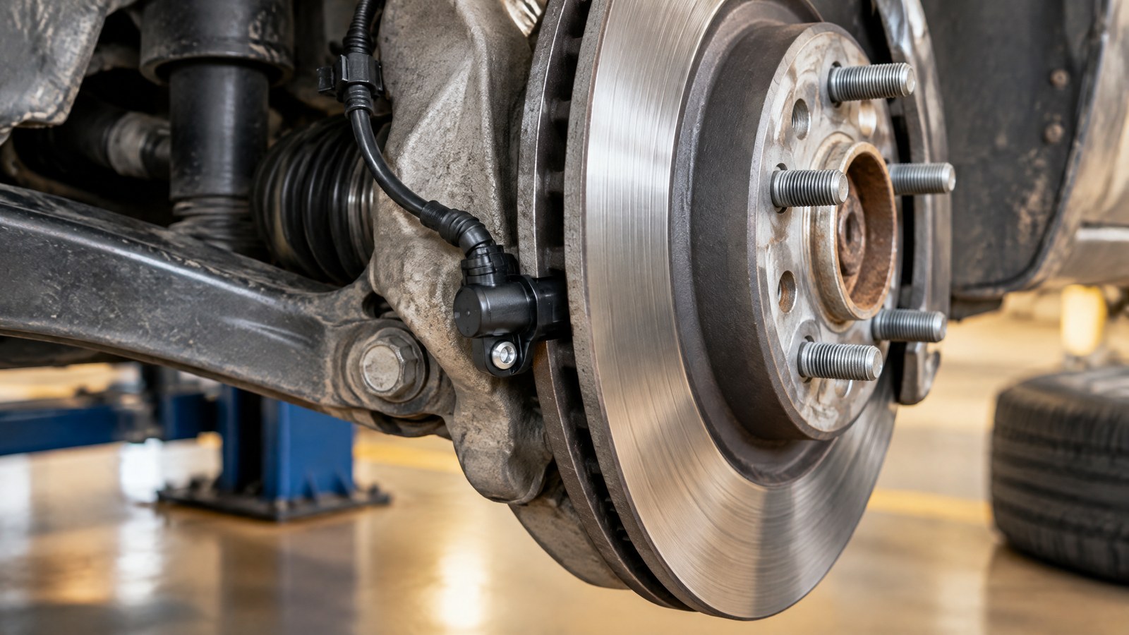
AI-generated editorial illustration of generic wheel-speed sensing hardware near a wheel hub, not a photograph of a tested product or an actual field measurement.
The key distinction is between rotation and ground travel. A rotating wheel creates a measurable pattern, while the meaning of that pattern depends on the vehicle’s movement, the other wheel readings and the control system’s wider context. That is why a wheel-speed sensor is best understood as one input in a safety-related measurement chain, rather than a standalone judge of whether a car is safe to drive.
From a Rotating Encoder to a Repeating Signal
The sensor normally sits beside a rotating encoder, also called a pulse wheel, tone wheel or ABS ring. Depending on the vehicle design, that encoder can be associated with the hub, brake disc, drive shaft or another part that turns with the road wheel. As teeth and gaps, or alternating magnetic poles, pass the sensor, they change the magnetic field at the sensing face. [1] [2]
The electronics turn those repeating changes into a signal. The control unit can use the timing or frequency of the pulses to estimate rotational rate: more cycles in a given time correspond to faster wheel rotation. This is a measurement of the rotating assembly, not a camera-like observation of the road.
Why Comparing Readings Matters
A single rotational value has limited meaning on its own. A wheel can rotate at a different rate while cornering, while passing over a changing surface, or when traction is changing. Brake and stability systems therefore interpret wheel-speed information together with other signals and vehicle-specific logic; a difference is evidence to be evaluated, not a universal diagnosis.
This framing avoids a common misunderstanding. The sensor does not measure tyre tread, brake-pad condition, water depth, or the exact grip available at the contact patch. It supplies rotation data, and the vehicle system decides how that data fits the situation.
Active and Passive Wheel-Speed Sensor Designs
Active and passive wheel-speed sensors differ mainly in how they create and deliver their signal. Both are intended to turn the motion of an encoder into information a control module can use, but their electronics, low-speed behaviour and possible capabilities are not the same. [1] [2]
Passive sensors generate an induced alternating signal
A conventional passive design uses a permanent magnet and a coil. Passing teeth and gaps alter magnetic flux through the coil, which induces an alternating voltage. The signal’s frequency changes with wheel rotation, and its amplitude is also related to speed. [2]
Because this approach depends on the changing magnetic field producing a usable signal, its lowest-speed performance is more limited than that of the active designs described by Apec. A passive sensor is a particular architecture, not a shortcut for judging the condition of any sensor simply by looking at a connector.
Active sensors process the magnetic pattern
Active sensors need an electrical supply. Hall-effect and magneto-resistive implementations can detect changes from a toothed or magnetic encoder and send a processed digital-style signal to the control unit. Bosch describes a Hall-based circuit that combines sensing, amplification and signal processing, with pulse frequency proportional to wheel speed. [1] [2]
That description explains why the word “active” matters: the sensor is more than a coil near a ring. It is powered electronics matched to a particular encoder and vehicle system. The fitted type and its expected signal are vehicle-specific technical details, so broad online descriptions should not be used as a test or replacement specification.
How ABS, Traction Control and ESC Use the Input
Wheel-speed data is especially valuable when a vehicle must distinguish ordinary rolling from a rapid change in wheel rotation. ABS uses that feedback in its effort to avoid wheel lock during braking, while traction-control and stability-related functions can use it as part of their own control strategies. [2] [3]
ABS uses rotational feedback during braking
Anti-lock braking systems are intended to help wheels maintain tractive contact while braking rather than remaining locked in rotation. The wheel-speed sensor supplies the rotation feedback that lets the brake-control module see relevant changes at the wheel. Apec notes that ABS function depends on wheel-speed sensors, while Pico describes their feedback role in ABS and derivative safety systems. [2] [3]
The practical limit is important: a sensor signal does not make a tyre create grip. It describes wheel motion, and the system’s performance still depends on the road, tyres, vehicle design and the situation.
ESC adds other measurements before it intervenes
On vehicles equipped with electronic stability control, wheel-speed information is only part of the picture. NHTSA explains that ESC monitors speed along with steering-wheel angle, yaw rate and lateral acceleration, then compares the driver’s intended course with the vehicle’s actual movement. [4]
This multi-sensor view is why it is misleading to describe a wheel-speed sensor as the sensor that “controls” stability. It contributes information; the ESC system evaluates multiple measurements and vehicle-specific logic. A warning involving these systems likewise cannot, by itself, identify one failed part.
Measurement Limits and Why Warning Lights Need Qualified Attention
A wheel-speed reading depends on the sensor, the encoder, the wiring path and the control module receiving a plausible signal. The sensor operates close to moving wheel hardware and in an exposed environment, so an alert associated with ABS or stability systems is a system-level clue rather than proof that the sensor itself is the cause. [2] [3]
The encoder and signal path are part of the measurement
The measurement chain includes more than the sensor head. Apec identifies issues involving a damaged, blocked or misaligned ABS ring and sensor position; Pico lists wiring, connector corrosion, damaged pulse-wheel features, ferrous contamination and excessive gap as possible causes of problematic signals. [2] [3]
These examples do not create a home diagnosis checklist. They show why a dashboard indication cannot fairly be reduced to “the sensor is bad.” A qualified assessment needs the correct vehicle information and should consider the complete measurement chain.
A warning lamp does not name the failed component
Pico notes that wheel-speed signals outside normal parameters may cause the control module to disable ABS and associated traction or stability functions and illuminate a warning light. That describes a protective system response to an implausible input; it does not prove a particular sensor, wheel bearing, connector or ring is at fault. [3]
Do not make braking-safety decisions from a general web explainer. Follow the vehicle manufacturer’s warning guidance and seek qualified human attention for warning lights, unusual brake behaviour or suspected safety-system faults before relying on the vehicle in demanding conditions.
Important Points / Key Information
Key Takeaways
- A wheel-speed sensor reports rotational motion near a wheel; it does not directly measure tyre grip or certify the vehicle’s safety.
- The encoder, sensor electronics, wiring and control module form one measurement chain, so a warning indication is not a part-by-part diagnosis.
- Passive sensors induce an alternating signal, while active Hall-effect or magneto-resistive designs use powered electronics to process magnetic changes.
- ABS, traction control and ESC can use wheel-speed input, but ESC also depends on measurements such as steering angle, yaw rate and lateral acceleration.
- Safety-related warning lights and unusual braking behaviour require vehicle-specific, qualified human review.
Examples / Supporting Information
The following examples explain interpretation rather than provide operating, testing or repair instructions.
Hypothetical Indian monsoon commute
Hypothetical example: during a rain-heavy commute, a vehicle may encounter standing water, painted markings, loose debris and changing traction in a short distance. A wheel-speed sensor can report a wheel’s changing rotation, but it cannot identify the water depth, inspect the tyre, or measure the surface’s exact friction. On an ESC-equipped vehicle, the wider system uses wheel-speed input with other measurements when interpreting vehicle motion. [4]
The useful lesson is not that electronics remove risk. It is that the sensor gives the vehicle a narrowly defined piece of motion information in conditions where context matters most.
A sourced active-sensor design example
Bosch describes an active design in which a Hall-based integrated circuit sees the changing magnetic field of a rotating multipole or steel encoder. The circuit processes that change into current impulses whose frequency is proportional to wheel speed. This is a clear example of the sensor translating nearby rotation into a signal; it is not evidence about any one car’s diagnosis or braking outcome. [1]
A sourced measurement-chain example
Apec places the sensor beside a pulse wheel that turns with the road wheel, while Pico highlights that sensors, pulse rings, connectors and circuits face vibration, movement and exposure. Together, those sources explain why the hardware around the sensor matters to the reading as much as the silicon inside it. [2] [3]
Conclusion
A wheel-speed sensor is a precise but limited observer: it converts a rotating encoder’s changing magnetic pattern into wheel-rotation data for brake and driving-management systems. Its value comes from how ABS, traction control or ESC interpret that data with other inputs, not from any ability to see road grip or diagnose a vehicle by itself. [1] [4]
For readers in India and elsewhere, the safest takeaway is simple: understand the sensor as part of an exposed, vehicle-specific measurement chain, and treat ABS or stability warnings as prompts for manufacturer-guided, qualified human review.
How we checked thisSources (4)
We keep source links private so your reading stays on techduopulse. Each note names the publisher and document we checked.
Bosch Mobility technical description of active non-contact wheel-speed sensing
Primary source · How a Wheel-Speed Sensor Turns Rotation Into DataApec Automotive guide to passive and active ABS sensor concepts
Secondary source · Active and Passive Wheel-Speed Sensor DesignsPico Technology explanation of Hall-effect wheel-speed feedback and signal-chain limits
Primary source · Measurement Limits and Why Warning Lights Need Qualified AttentionNHTSA explanation of ESC’s multi-sensor vehicle-motion assessment
Primary source · How ABS, Traction Control and ESC Use the InputOwner-approved educational sensor explainer; obsolete private-draft status removed without changing source-backed facts or professional safety boundaries. Original generic AI editorial illustration, not a product or field-test photograph.