
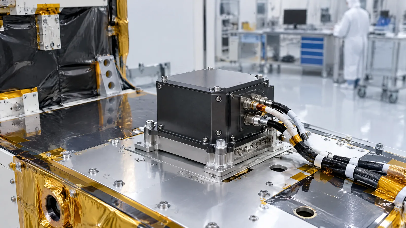
When a satellite must keep an Earth-observation camera or communications antenna pointed correctly, a single motion reading is not enough. A satellite IMU measures three-axis angular velocity and linear acceleration, giving the spacecraft control system inertial motion data while other sensors and software establish the wider attitude solution.
This article is part of the computer hardware technology guide library.
Key takeaways
A satellite IMU is an integrated unit, not one physical sensor type. A common six-axis arrangement combines three gyroscope axes with three accelerometer axes, although the exact mix is mission-specific.
The gyroscopes report rotation rate and the accelerometers report linear acceleration or specific-force-related data along the unit’s axes. Processing can use both streams to estimate changing motion.
An IMU does not automatically provide an absolute spacecraft attitude, a complete orbit solution or a reliable position by itself. Star trackers, Sun or Earth sensors, magnetometers, GPS and mission software may provide complementary references.
Bias, temperature, vibration, mounting alignment and sensor noise affect the result. Spacecraft designers choose the sensor mix, redundancy and filtering for the mission’s pointing and reliability needs.
- Integrated inertial unit, not a single sensor
- Measures rotation rate and linear acceleration across axes
- Supports the control loop but is not the whole attitude-control system
- Needs calibration, processing and mission context
What is a satellite IMU?
An inertial measurement unit, or IMU, is a package that combines inertial sensors so a vehicle can observe its own motion. In the common six-axis description, three gyroscope axes measure angular velocity and three accelerometer axes measure linear acceleration along three perpendicular directions. Some units also include a temperature sensor or processing and compensation functions, but those features should not be assumed for every model.
This distinction matters because an IMU is not the same as an accelerometer module or a gyroscope alone. An accelerometer contributes translational-motion data; a gyroscope contributes rotational-rate data. The integrated unit makes both streams available in a coordinated frame, while the spacecraft computer decides how to use them.
The unit’s X, Y and Z axes belong to the IMU’s physical mounting and reference frame. They are not automatically north, east and up. Installation alignment, calibration and the spacecraft’s coordinate conventions determine how those readings are interpreted.
What does a satellite IMU measure?
The gyroscope part measures angular velocity: how quickly the spacecraft is rotating about each sensing axis. The accelerometer part measures linear acceleration or specific force along its axes. Together, the streams describe short-term changes in the spacecraft’s motion and rotation rather than directly photographing its orientation or reading its position from space.
A control computer can integrate and filter these measurements to maintain an estimate of attitude and motion. The exact output may be raw sensor data, calibrated rates and acceleration, or a higher-level state estimate produced by software. The IMU itself should not be credited with every calculated value that appears elsewhere in the spacecraft system.
Temperature data is another example of a possible supporting measurement. Temperature changes can alter sensor bias and scale, so a unit or its electronics may use temperature information for compensation. Whether that sensor and compensation are inside the IMU, outside it or absent depends on the design.
| Part or subsystem | Typical measurement or role | What it does not guarantee |
|---|---|---|
| Gyroscope axes | Angular velocity about the unit’s axes | Absolute attitude without an external reference |
| Accelerometer axes | Linear acceleration or specific-force-related data | A complete orbit or position solution by itself |
| Optional temperature sensor | Thermal information that can support compensation | Identical thermal behaviour across all IMU models |
| Spacecraft software | Calibration, filtering, fusion and control calculations | A result that is independent of sensor quality and alignment |
How does a spacecraft use an IMU for attitude control?
A spacecraft attitude-and-orbit-control system combines sensors, software and actuators. The IMU supplies inertial motion information to the system; the computer compares the estimated state with the desired pointing and sends commands to the spacecraft’s selected actuators. The actuators might be reaction wheels, magnetic torquers or another mission-specific device. They are external components, not physical parts that every IMU contains.
Inertial data is especially useful when the spacecraft is rotating, during short manoeuvres or when another reference is temporarily unavailable. NASA’s GRACE-FO description, for example, lists an IMU alongside a star tracker, gyro package, Earth and Sun sensor, magnetometer and GPS receiver. That system-level list shows why a satellite IMU should be understood as one contributor within a larger architecture.
The control system may smooth, average or fuse data. A higher-accuracy spacecraft can require better gyros and external references such as star or horizon sensors. A smaller or less demanding mission can make different trade-offs. There is no universal satellite IMU configuration that fits every orbit, payload or pointing requirement.
Why an IMU cannot measure everything alone
Inertial measurements are relative to the unit’s starting state and are affected by bias and noise. Integrating small errors over time can make an estimated attitude or motion state drift. A gyroscope does not know an absolute star-based orientation merely because it measures rotation, and an accelerometer does not become a GPS receiver because it measures acceleration.
External references close that gap. A star tracker can determine orientation against stars. A Sun or Earth sensor can provide a coarse reference in suitable viewing conditions. A magnetometer can compare the local magnetic field with a model, while GPS can provide orbital position and, in some configurations, attitude-related information. The choice and combination depend on mission requirements.
This is also why the phrase ‘the satellite IMU controls the spacecraft’ is incomplete. The IMU provides measurements. Software estimates state and computes control actions, while separate actuators apply torque or force. A failure in any one part can change the overall behaviour, so an IMU data sheet is not a safety or pointing guarantee for an assembled spacecraft.
Accuracy limits and mission-specific design choices
IMU readings are shaped by sensor bias, noise, cross-axis effects, temperature, vibration, mounting alignment, sampling and calibration. NASA’s spacecraft guidance notes that MEMS gyro bias can vary with temperature, which is one reason demanding missions may combine inertial data with better external references and filtering. The relevant specification is always the one for the selected flight unit under its stated conditions.
Redundancy is optional rather than universal. NASA TechPort describes a distributed IMU project for space robotics and CubeSats in which additional sensors can support measurement resolution and fault detection. That is a particular architecture, not evidence that every commercial or flight IMU has duplicated sensors or can isolate failures on its own.
For readers comparing spacecraft concepts, the useful questions are: Which axes are measured? What is the gyro and accelerometer performance under temperature and vibration? How is the unit aligned and calibrated? Which external references correct drift? Which computer performs the estimation? And what happens if one measurement becomes unavailable? Those questions reveal more than the label ‘space IMU’ alone.
Satellite IMU FAQs
These answers describe the common system concept. A real satellite’s interface, sensor count, calibration method and control architecture remain mission-specific.
Is a satellite IMU one sensor?
No. An IMU is an integrated unit containing multiple inertial sensors. A common six-axis design combines three gyroscope axes and three accelerometer axes, although the exact configuration can vary.
Does a satellite IMU measure attitude directly?
It measures inertial motion, especially angular velocity and linear acceleration. Software can use those measurements in an attitude estimate, but absolute attitude usually needs an external reference such as a star tracker, Sun or Earth sensor, magnetometer or another mission-specific source.
What is the difference between a satellite IMU and an accelerometer?
An accelerometer measures acceleration along its available axes. An IMU combines accelerometers with gyroscopes and may include other support features, so it can provide both linear-acceleration and angular-rate data to the spacecraft system.
Does every satellite IMU include a temperature sensor?
No. Temperature sensing and thermal compensation are common design considerations, but whether they are inside the IMU or handled elsewhere depends on the selected unit and spacecraft architecture.
Does the IMU contain the spacecraft thrusters or reaction wheels?
No. Those are actuators in the wider attitude-and-orbit-control system. The IMU supplies measurements; separate electronics and control software use them to command the mission’s chosen actuators.
About the image
AI-generated editorial illustration; not an actual product or mission photograph.
Source notes
Reporting record
techduopulse stores source destinations privately. Public notes remain non-clickable so every visitor journey stays on this website.
Source note: NASA/JPL GRACE-FO attitude and orbit control system
Primary source · System components, three-axis control, spacecraft rates, and complementary star, Earth/Sun, magnetic and inertial sensorsSource note: NASA technical guidance on spacecraft attitude determination and control
Primary source · Gyro role and limits, external attitude references, sensor selection, filtering, temperature-dependent biasSource note: Epson Sensing Device IMU technical explanation
Primary source · Three-axis angular velocity and acceleration, six-axis configuration, optional temperature data, satellite stabilization and control applicationSource note: NASA TechPort distributed IMU technology project
Primary source · Co-located accelerometers and gyroscopes, optional distributed redundancy and space-constrained spacecraft applicationsNew satellite application explainer distinct from the existing accelerometer and gyroscope guides. Defines the IMU as an integrated inertial system, separates optional temperature sensing and mission-specific redundancy from the core concept, explains its place in a larger attitude-control loop, and qualifies drift, external references and actuator boundaries without unsupported performance claims.


