During a rocket-engine test, a pressure trace can look normal while a valve actuator has not travelled as expected. A valve-actuator position transducer measures where the actuator or valve mechanism is, so engineers can compare that position with pressure, flow and temperature records; it does not open the valve or decide when to move it.
This article is part of the emerging technology science guide library.
What does a rocket valve position sensor measure?
A rocket valve position sensor is a position instrument attached to, or mechanically associated with, an actuator or valve mechanism. It converts travel or angular position into a signal that a test data system can record. The useful question is not simply whether the valve is labelled open or closed, but where the mechanism was during a test event and how that trace relates to other measurements.
NASA Stennis lists position channels among the low-speed measurements used in rocket-engine hot-fire testing, alongside pressure, flow, temperature, thrust and string pots. That establishes position as a recorded test quantity, not a universal part number or a claim that every launch vehicle uses the same sensor.
- The actuator or valve mechanism supplies the physical movement being observed.
- The transducer converts movement into a continuous or otherwise interpretable signal.
- Signal conditioning and the data-acquisition system supply, scale, time-stamp and store the reading when the installation requires them.
- The test team compares position with related pressure, flow and temperature channels.
Position transducer, valve, actuator and control system are different things
These terms are easy to mix up. The valve regulates a fluid path. The actuator supplies the movement that changes the valve state. The position transducer reports movement. A controller or command system, if present, decides how a system should respond. A data-acquisition system records measurements; it is not automatically a controller.
A string potentiometer, often called a string pot, is one possible position instrument. A rotary or linear position transmitter is another possible approach. A simple limit switch may instead provide a discrete state such as open or closed. These are model-specific choices. A discrete indication can confirm that a threshold or end position was reached, but it does not provide the same travel history as a continuous position measurement.
- Continuous position: useful for seeing travel, intermediate position and timing during a test.
- Discrete position: a separate on/off or 0/1 indication, often used for a limit or status condition.
- Control output: an external command or feedback path that this article does not specify.
How the position channel fits into rocket testing
The position channel is most useful when viewed beside other time-aligned measurements. For example, a test record may show an actuator-position change alongside a pressure response, a flow change and a temperature trend. A mismatch can prompt engineers to investigate timing, mechanical travel, instrumentation behaviour or another part of the test setup. The position trace is evidence for analysis; it is not, by itself, proof of the internal condition of every valve component.
NASA Stennis describes a low-speed acquisition system with time-stamped measurements and lists string pots and position among its channels. The same presentation separates those channels from high-speed vibration and dynamic-pressure measurements and from discrete open/closed channels. That distinction matters: the appropriate sample rate, wiring and signal conditioning depend on the measurement and the facility, rather than on the word sensor alone.
In a real installation, the transducer may be external to the fluid boundary and may observe actuator travel through a linkage or shaft arrangement. The exact arrangement is model-specific. The sensor should not be assumed to touch propellant, to measure flow directly or to be suitable for flight simply because it was used during a ground test.
Why calibration, drift and installation quality matter
A position reading is only useful when the team understands its uncertainty and failure modes. NASA’s launch-vehicle instrumentation guidance recommends considering metrology and error budgets early, planning calibration and compensation, and designing sensors, connectors and wiring to resist contamination, leakage, shorts, insulation damage and vibration-related deterioration.
Position instruments can also drift or wear. NASA specifically notes that long-term transducer stability is a concern and uses potentiometer-wiper wear as an example of a failure mechanism that active redundancy may not solve when multiple elements experience the same condition. The practical lesson is to verify the complete measurement chain and its environment instead of assuming that adding a second identical element removes every risk.
The same guidance calls for verification plans and says changes to instrumentation should be supported, as appropriate, by analysis, similarity, laboratory verification and hot-fire testing. Those are program-level practices, not a DIY test recipe. A project’s qualification, calibration and acceptance requirements must come from its responsible engineering and safety authorities.
- Define the travel or angle range and the required measurement uncertainty.
- Account for mechanical linkage, mounting stiffness, vibration, temperature and connector or cable effects.
- Keep calibration records and check for drift, offset or loss of signal.
- Separate a sensor change from a control-system change; they have different verification consequences.
What this sensor cannot tell you on its own
A position signal does not directly measure pressure, mass flow, temperature, leakage, valve-seat condition or actuator force. A mechanism can reach a reported position while another part of the system behaves differently from the expected model. That is why position is normally interpreted with other channels and with knowledge of the mechanical arrangement.
It also does not automatically provide a safe command path. NASA distinguishes open-loop transducer applications, which report system performance, from closed-loop applications that regulate a system using transducer output. This article stays with the observation and test-recording use. It does not recommend connecting a position sensor to propulsion controls or changing a launch-vehicle design.
Key takeaways
A valve-actuator position transducer records where a mechanism is during a test. NASA includes position among rocket-engine hot-fire instrumentation channels, but the technology and installation are project-specific. Treat the transducer, actuator, valve, signal conditioning, data acquisition and control logic as separate parts, and interpret position beside pressure, flow and temperature rather than treating one trace as a complete diagnosis.
- A string pot or position transmitter is an optional implementation, not a universal rocket component.
- Open/closed limit indications are discrete status signals and are not the same as continuous travel data.
- Calibration, drift, vibration, contamination and wiring deserve attention across the full measurement chain.
- Ground-test instrumentation does not automatically equal flight-qualified hardware or a control sensor.
Frequently asked questions
Is a rocket valve position sensor the same as a valve actuator?
No. The actuator moves the mechanism, while the position transducer reports that movement. The valve regulates a fluid path, and a separate command or control system may govern actuator operation.
Does a position sensor measure rocket propellant flow?
No. It measures position or travel. Flow requires a separate flow-measurement channel; pressure and temperature also normally require their own instruments.
Is a string potentiometer used on every launch vehicle valve?
No. NASA’s hot-fire presentation lists string pots and position channels, but it does not establish one universal technology. A project may use a different position transmitter, a discrete limit device or another qualified arrangement.
Can the position signal control a valve automatically?
It can be part of a closed-loop system only when the responsible design explicitly uses it that way. A recorded test channel is not automatically a control input, and closed-loop use has different failure consequences from open-loop monitoring.
Why compare actuator position with pressure and flow?
Time-aligned channels help engineers assess whether a movement occurred when expected and whether related system responses match the test interpretation. Position alone cannot identify every mechanical or fluid-system condition.
About the image
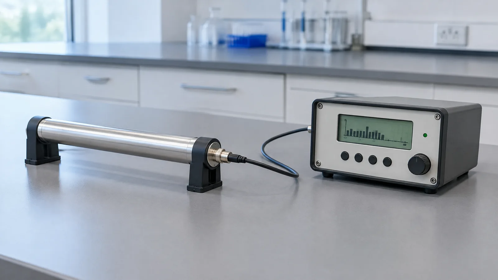
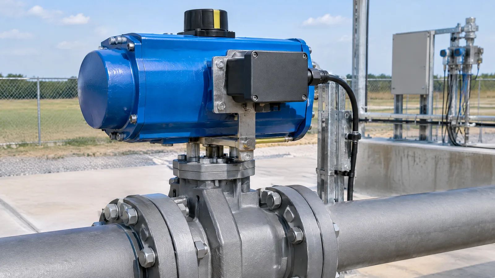
AI-generated editorial illustration; not an actual product or mission photograph.
Source notes
Reporting record
techduopulse stores source destinations privately. Public notes remain non-clickable so every visitor journey stays on this website.
Source note: NASA Stennis Space Center rocket-engine hot-fire sensor presentation
Primary source · Position, string-pot, transmitter, discrete and data-acquisition channels in hot-fire testingSource note: NASA Lessons Learned launch-vehicle instrumentation reliability guidance
Primary source · Metrology, calibration, drift, installation, verification and open-loop versus closed-loop transducer useInitial 15 October 2026 India-facing explainer. Uses two supplied NASA primary sources to distinguish a valve-actuator position measurement channel from the valve, actuator, data system and control logic; qualifies optional position technologies and separates continuous position from discrete status. Excludes build, propulsion-control and flight-qualification claims not supported by the sources.