
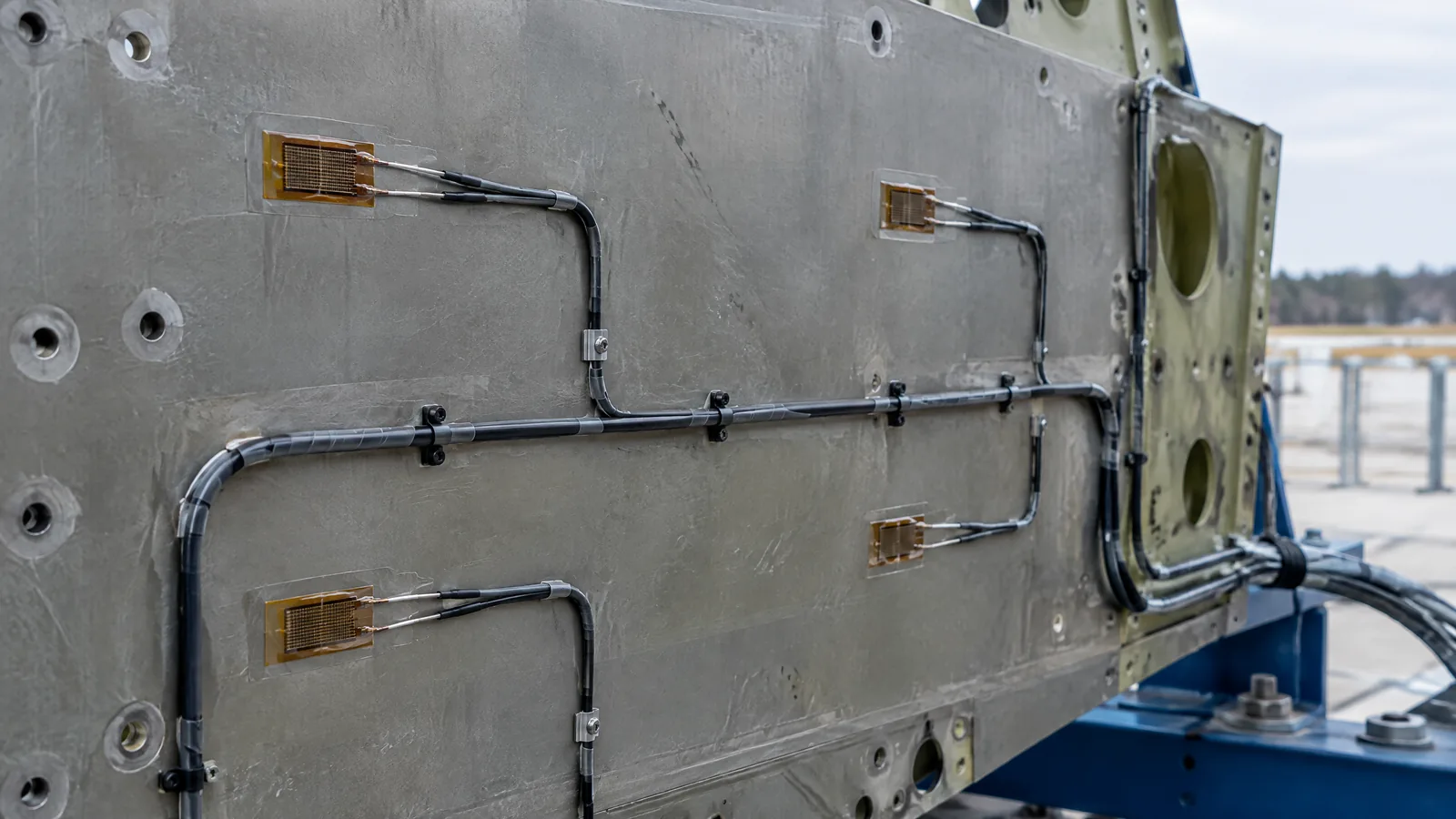
When engineers need to know whether a launch-vehicle structure is responding as predicted during development flight, a camera alone cannot show the tiny deformation of the material. A structural strain gauge measures that local surface deformation and turns it into an electrical signal for the flight-test data system; it does not measure force or load directly.
This article is part of the computer hardware technology guide library.
Key takeaways
A structural strain gauge is a bonded resistive transducer that responds to small changes in surface strain, meaning deformation relative to the material's original length.
In rocket development flight instrumentation, strain data can help engineers compare a real vehicle response with structural and loads models.
Strain is not the same as force or load. A load estimate needs the structure's geometry, material behaviour, loading assumptions, calibration and a complete measurement chain.
A conventional metallic gauge and an optional fiber-optic sensing system are different instrumentation approaches; one should not be described as the other.
- Measures local deformation, not force directly.
- Usually appears as one part of development flight instrumentation.
- Readings depend on the structure, electronics, timing and test state.
- The sensor alone cannot certify a vehicle design or a safe load limit.
What does a structural strain gauge measure?
A structural strain gauge measures strain: a small change in length or shape at the surface where the transducer is part of the measurement system. In a bonded resistive design, deformation changes the gauge's electrical resistance. Data-acquisition electronics detect that small change and record it as a time-varying measurement.
That makes a strain gauge different from a force sensor used in a weighing or test fixture. The gauge is responding to what happens to the material at its local measurement area. NASA's launch-vehicle flight-instrumentation guidance lists strain among the physical phenomena that sensors can transduce into electrical signals, alongside vibration, acceleration, temperature and pressure.
How is a rocket strain gauge used in flight instrumentation?
A rocket strain gauge is normally part of a wider development flight instrumentation, or DFI, system. NASA describes DFI as a vehicle-level way to collect test data when engineering models still contain uncertainty. The system can include sensors, data-acquisition units, signal conditioning, timing, telemetry, harnesses and recording equipment. The gauge contributes one measurement; it is not the entire instrument chain.
During a development flight, recorded strain can be compared with predicted structural response. The purpose is measurement and model validation: engineers can investigate whether the real vehicle response agrees with the assumptions used in design and analysis. That information can also be considered with other measurements, such as acceleration or pressure, when reviewing the vehicle's behaviour.
NASA's Ares I-X lessons describe a practical limitation: strain-gage readings were affected by the vehicle's integration state, and some gauges had so much induced strain during stacking that the data system could not zero them. This does not provide a universal failure rule, but it shows why the condition of the assembled test article and the timing of instrumentation work matter to the meaning of the data.
Strain versus load: why the terms are not interchangeable
Strain describes deformation. Load describes an applied force or the force carried through a structural path. A structure may develop strain when it is loaded, but the gauge does not know the complete force by itself. The relationship between local strain and an overall load depends on the structure's shape, material, boundary conditions, direction of loading, temperature and the model or calibration used to interpret the measurement.
For that reason, a strain trace should not be presented as a direct reading in newtons without the supporting engineering relationship. A local surface value may help indicate bending, tension or compression in that area, while a vehicle-level load estimate may require multiple measurements and a validated structural model. NASA's FOSS material makes the same broader point about development instrumentation: flight data can reduce uncertainty in predicted loads and dynamic responses and help update models.
The safe beginner rule is simple: say that the gauge measures strain unless the source and measurement method explicitly support a derived load quantity. Do not infer a vehicle load limit from a sensor label or from one graph.
| Term | What it describes | What a reader should not assume |
|---|---|---|
| Strain | Local deformation or change in shape relative to the material | It is not automatically a force value |
| Load | Force carried or applied through a structural system | It cannot be read from one gauge without a supported relationship |
| Flight instrumentation | The connected sensors, acquisition, timing and recording system | The gauge alone is not the complete measurement setup |
What else is needed to make the reading useful?
The useful result comes from the measurement chain, not the gauge in isolation. A compatible excitation and signal-conditioning path must resolve the small resistance change. The acquisition system must sample and time-stamp the channel in a way that can be compared with other flight data. Engineers also need to understand the test article's condition, the relevant structural model and the calibration or interpretation method used for that channel.
Temperature, vibration, wiring, electrical noise, integration sequence and mechanical changes can all affect how a measurement is interpreted. The NASA Stennis sensor presentation places strain gages in a high-speed data-acquisition system alongside accelerometers and dynamic-pressure channels. That example is facility-specific, so it should not be treated as a universal sample rate, wiring scheme or hardware recipe for every launch vehicle.
A measurement can be technically recorded and still be difficult to interpret if its zero, timing or structural context is unclear. This is why flight-test instrumentation planning begins with the question being investigated, rather than with a sensor name alone.
Conventional gauges and optional fiber-optic sensing
A conventional structural strain gauge is a bonded resistive transducer. Fiber-optic sensing is a separate approach that can use technologies such as Fiber Bragg Grating and optical frequency-domain reflectometry. NASA's FOSS research describes fiber-optic systems for aerospace measurements and identifies launch vehicles as an application area, while also presenting them as an alternative to conventional strain gauges.
The distinction matters because capabilities, packaging, readout and deployment are model-specific. A fiber-optic system may support many sensing points or additional measurements in a particular research configuration, but those capabilities must not be attributed to every metallic strain gauge. Likewise, a sensor described as a strain gauge should not be assumed to measure temperature, acceleration or distributed shape unless its documented system does so.
Both approaches belong to the broader family of structural test instrumentation. The choice depends on the test question, vehicle environment, data system and program requirements. This article does not prescribe a component, installation method or vehicle design.
Limitations a beginner should remember
A strain gauge reports a local response. One channel cannot describe every stress or load in a launch vehicle. Its reading also does not prove that a design is safe, flight-ready or within an allowable limit.
The sensor is sensitive to the complete test context. Assembly state, thermal conditions, signal conditioning, timing and data-quality checks can change what an engineer can conclude. NASA's Ares I-X account is useful precisely because it records an integration-related zeroing problem rather than pretending that a gauge always produces a clean value.
Finally, strain data is not a substitute for professional structural analysis, qualification or range safety practice. Readers can understand the measurement principle without attempting to bond sensors to a propulsion system or draw safety conclusions from a hobby setup.
Frequently asked questions
These answers describe the measurement concept and the documented development-flight context. Exact hardware and interpretation remain specific to the vehicle and test program.
What does a rocket strain gauge measure?
It measures local structural strain, or small surface deformation, by turning a change in the transducer's resistance into an electrical signal. It does not measure force directly.
Is strain the same as load in a launch vehicle?
No. Strain describes deformation, while load describes force carried through a structure. A load estimate needs a supported structural relationship, calibration or model, and appropriate context.
Why are strain gauges used in rocket flight tests?
They can provide structural-response data for development flight instrumentation. Engineers may compare the measured response with predictions and use the evidence to investigate model uncertainty.
Is a fiber-optic strain sensor the same as a bonded resistive gauge?
No. Fiber-optic sensing is a separate instrumentation approach. NASA describes it as an alternative research and flight-technology path, with capabilities that depend on the specific system.
Can one strain-gauge reading prove a rocket is safe?
No. One local measurement cannot establish vehicle safety or a load limit. Those conclusions require qualified analysis, test evidence, system context and the responsible engineering and safety processes.
About the image
AI-generated editorial illustration; not an actual product or mission photograph.
Source notes
Reporting record
techduopulse stores source destinations privately. Public notes remain non-clickable so every visitor journey stays on this website.
Source note: NASA launch-vehicle development-flight-instrumentation design paper
Primary source · DFI purpose and hardware; sensors transduce strain and other physical phenomena; Ares I-X strain-gage integration and zeroing lessonSource note: NASA Stennis Space Center rocket-engine hot-fire sensor presentation
Primary source · Strain gages listed in high-speed rocket-test data acquisition alongside accelerometers and dynamic pressuresSource note: NASA fiber-optic sensing technology briefing
Primary source · Conventional strain-gage comparison; FBG/OFDR structural sensing; DFI data for loads and dynamics model validationInitial 15 October 2026 India-facing technical explainer. Uses three supplied NASA primary documents to define a structural strain gauge, place it within development flight instrumentation, distinguish strain from load, separate conventional bonded resistive gauges from optional fiber-optic systems, and state integration and interpretation limits without DIY propulsion or safety advice.


