
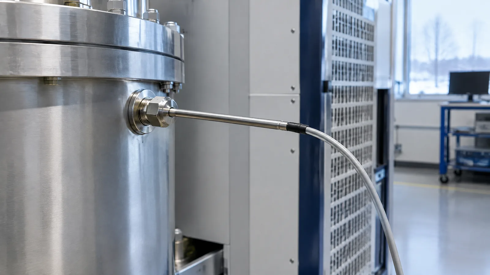
A rocket test team may need a steady temperature reading at a test point while hot gases, cryogenic fluids, vibration and long cables make the measurement difficult. A rocket RTD temperature sensor measures temperature through the predictable change in a metal element's electrical resistance, then relies on signal conditioning and calibrated data acquisition to turn that change into a useful test value.
This article is part of the computer hardware technology guide library.
What a rocket RTD temperature sensor measures
An RTD, or resistance temperature detector, is a temperature transducer: its sensing element changes electrical resistance as temperature changes. The instrument measures that resistance-related signal and applies the appropriate conversion so engineers can examine the temperature at a defined location.
The RTD element is not the whole measurement system. A practical test installation also has a probe or package, connectors and cable, a signal-conditioning circuit, a data-acquisition channel, calibration information and software that scales the signal. Keeping these roles separate avoids calling the logger or controller a sensor, or assuming that a bare resistance element is ready to connect to any instrument.
NASA's Stennis Space Center presentation lists RTDs among the low-speed measurements used in rocket-engine hot-fire testing, alongside thermocouples, pressure, thrust, flow and position measurements. That is evidence of an instrumentation application, not a claim that every rocket or every test point uses an RTD.
- Sensing element: the resistance-changing metal element at the measurement tip.
- Probe or package: the mechanical part that places and protects the element.
- Signal conditioning: electronics that provide excitation and interpret the small electrical signal.
- Data-acquisition system: the instrument that records, time-stamps and presents the measured value.
How an RTD signal becomes a rocket-test reading
The basic signal path is straightforward. A conditioning circuit supplies a known current through the RTD; because the element's resistance varies with temperature, the resulting voltage changes as the temperature changes. The conditioning electronics measure that voltage, and the acquisition system scales it using the sensor's calibration information.
In the Stennis example, NASA describes a 1 mA constant current, voltage measurement and scaling using ITS-90 coefficients from the sensor calibration report. ITS-90 is a recognised temperature-scale framework; in this context, the coefficients are the conversion information associated with the calibrated sensor rather than a universal formula that makes every RTD interchangeable.
The example also shows why a stable reading depends on more than the element. NASA describes an overall distance of about 300 feet from the RTD installation to signal conditioning in that setup, with the sensor purchased for an appropriate length. Cable length, connectors, electrical noise, thermal mounting and the conditioning channel all belong in the measurement review.
- Temperature changes the RTD element's resistance.
- A known excitation current produces a related voltage signal.
- Signal conditioning reads and prepares the voltage for acquisition.
- Calibration coefficients and the acquisition system convert the signal into engineering units for analysis.
RTD versus thermocouple in rocket tests
An RTD and a thermocouple both report temperature, but they do not measure it in the same way. An RTD uses resistance change in a metal element. A thermocouple uses the small thermoelectric voltage produced by two dissimilar metals and needs appropriate reference-junction treatment for an absolute temperature reading.
The choice follows the measurement need, installation and qualified system design. The NASA Stennis presentation describes RTDs as a more accurate and more rugged option in its example, but also notes higher cost and longer procurement lead time there. It separately identifies E-type thermocouples for cryogenic temperature applications and K-type thermocouples for hot-temperature applications. Those facility-specific examples should not be turned into a universal rule that an RTD is always better or that every RTD is cryogenic-rated.
For a beginner, the useful distinction is this: an RTD can be attractive when stability, repeatability and a controlled resistance measurement matter; a thermocouple can be attractive when its temperature range, construction and installation suit the point. The probe, cable, interface and calibration method may matter as much as the sensor family.
| Question | RTD | Thermocouple |
|---|---|---|
| Electrical principle | Temperature-dependent metal resistance | Thermoelectric voltage from dissimilar metals |
| What the interface must handle | Excitation, resistance-to-temperature scaling and lead effects | Small voltage, reference-junction treatment and suitable thermocouple wiring |
| Rocket-test lesson | Use the calibrated element, length and conditioning path as one system | Choose the thermocouple type and installation for the intended temperature point |
Why calibration and installation discipline matter
A temperature number is only useful when the measurement chain is understood. NASA's launch-vehicle instrumentation lesson recommends considering metrology, error budgets, calibration and compensation early in the design. It also stresses controlled manufacturing, inspection, contamination prevention and protection against wiring damage, insulation problems and vibration-related deterioration.
For an RTD, calibration information must travel with the sensor and its measurement context. The Stennis presentation describes using a precision resistor substitution to verify the amplifier and scaling operation. That check exercises the signal-conditioning path; it does not by itself prove that the probe is sensing the temperature of the intended hardware. Thermal contact, placement, response time and local heat paths still affect the result.
The NASA lesson also identifies long-term transducer drift as a reliability problem and recommends testing assembled transducers under appropriate environmental conditions, including temperature cycling where relevant. These are engineering and verification practices for qualified aerospace programmes, not a home experiment or a wiring recipe.
- Confirm that the sensor calibration record matches the element and installation.
- Check the entire signal path, not only the displayed number.
- Consider thermal placement, vibration, contamination, connectors and insulation as part of the measurement.
- Treat any change to a qualified aerospace instrumentation system as a controlled engineering change requiring appropriate analysis and verification.
What an RTD can and cannot tell a test team
An RTD reports the temperature experienced at its sensing location, within the accuracy and response limits of the complete instrument. It can help a test team compare temperature behaviour across a run, examine a stable test point or correlate temperature with other recorded channels. It does not automatically reveal the temperature everywhere in an engine, tank, feed line or vehicle.
The distinction between an observation channel and a control or protection channel is important. NASA's launch-vehicle lesson separates open-loop transducer applications, which provide information about system performance, from closed-loop applications that regulate a system. A sensor used for one purpose must not be assumed suitable for automatic shutdown, propulsion control or crew protection without the required qualified design and verification.
RTDs also do not make a cryogenic measurement safe or valid by name alone. Cryogenic service can impose requirements on the element, package, materials, cable, connector, calibration and installation. The supplied NASA example specifically names a thermocouple type for cryogenic temperature applications, so the careful conclusion is to verify the exact sensor and test configuration rather than generalise from the RTD label.
Key takeaways
A rocket RTD temperature sensor measures temperature through a metal element's resistance change; the probe, conditioning circuit, calibration data and acquisition channel complete the measurement.
NASA documents RTDs as one of the low-speed measurements used in a rocket-engine hot-fire test environment, with constant-current excitation, voltage scaling and calibration-based conversion in its example.
RTD and thermocouple are different sensor families. The right choice depends on the temperature point, installation, response, wiring, calibration and qualification—not on a universal ranking.
A reading from an RTD is an observation of its installed point, not automatic evidence that the whole propulsion system has the same temperature or that the channel is approved for control.
- Use the complete measurement chain as the unit of understanding.
- Separate optional or model-specific hardware from the physical sensing element.
- Keep cryogenic suitability and control-system use tied to documented engineering requirements.
Frequently asked questions
These answers describe the documented test-instrumentation concepts without turning them into component-selection or operating instructions.
What does an RTD measure in a rocket test?
It measures temperature at its installed sensing point by detecting the predictable change in resistance of a metal element. The result depends on the probe, wiring, signal conditioning, calibration information and data-acquisition channel as well as the element.
Is an RTD the same as a thermocouple?
No. An RTD measures resistance change in a metal element. A thermocouple produces a thermoelectric voltage from dissimilar metals and requires appropriate reference-junction treatment. They are separate sensor families with different installation and interface considerations.
Are all RTDs suitable for cryogenic rocket testing?
No. Cryogenic suitability depends on the exact element, package, materials, cable, connector, calibration and qualified installation. The NASA source supplied for this topic identifies an E-type thermocouple for cryogenic applications in its facility example, so an RTD label alone is not proof of cryogenic qualification.
Why does an RTD need signal conditioning?
The resistance change must be excited and measured accurately. In NASA's Stennis example, a constant current produces a voltage that the conditioning system reads and scales using calibration coefficients before the data-acquisition system records it.
Can an RTD reading control a rocket engine?
Not automatically. A test channel may simply observe and record a temperature, while a closed-loop control or protection channel needs a separately qualified system design, failure analysis, verification and operational approval.
About the image
AI-generated editorial illustration; not an actual product or mission photograph.
Source notes
Reporting record
techduopulse stores source destinations privately. Public notes remain non-clickable so every visitor journey stays on this website.
Source note: NASA Stennis Space Center rocket-engine hot-fire sensor presentation
Primary source · RTD measurement principle, low-speed acquisition, constant-current excitation, ITS-90 scaling, calibration verification and facility-specific RTD/thermocouple examplesSource note: NASA Lessons Learned launch-vehicle instrumentation reliability guidance
Primary source · Integrated instrumentation design, metrology, calibration, contamination and vibration controls, verification, drift, and open-loop versus closed-loop transducer contextNew application-specific hardware explainer for rocket-engine and launch-vehicle test instrumentation. It extends the existing general temperature-sensor guide without duplicating it, uses two supplied NASA primary sources, distinguishes RTD elements from probes, conditioning and acquisition instruments, and qualifies cryogenic and control-system claims.


