
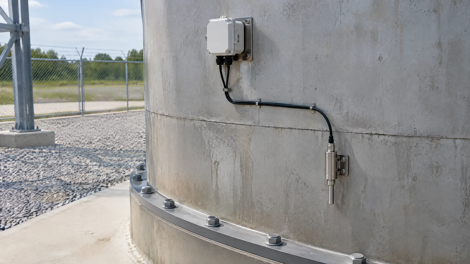
A rocket-engine leak cannot be judged safely from one surprising reading: a leak may appear as liquid droplets or vapour, while evaporation can create a temperature change shaped by the surrounding environment. A rocket propellant leak detector sensor in ESA’s proposed concept combines electrical conductivity with temperature measurement to look for those clues together, while the wider instrumentation system supplies signal handling, verification and fault-detection context.
This article is part of the computer hardware technology guide library.
What is a rocket propellant leak detector sensor?
In this topic, “sensor” is shorthand for an integrated leak-detection device, not one universal component sold for every launch vehicle. ESA describes a proposed rocket-engine device that combines conductive electrodes, multiple temperature sensors, a flow-passage structure and the electronics or logic needed to signal a possible leak.
The distinction matters. The electrode wires and temperature elements are the physical sensing parts. The annular housing and inner flow passage are the mechanical device. Signal conditioning, comparison rules, telemetry and fault-detection, isolation and recovery (FDIR) logic belong to the surrounding instrumentation system. NASA’s launch-vehicle guidance treats those parts as a connected engineering lifecycle rather than as an isolated sensor purchase. [R1]
ESA presents this as a concept seeking implementation and licensing partners. It should therefore be read as a specific technical approach, not as proof that all rockets use this arrangement or that one design fits every propellant and engine. [R6]
- Physical sensors: conductive wires and temperature-sensing elements.
- Device hardware: a leak-tight flow-passage assembly designed for a rocket-engine environment.
- Instrumentation: excitation, signal conditioning, comparison, telemetry and fault indication.
- System response: a qualified engineering and FDIR process decides what a signal means; this article does not prescribe an automatic control action.
How the combined conductivity and temperature approach works
The first channel looks for electrical contact. ESA’s concept places conductive wires across the flow passage. If liquid propellant droplets touch two or more wires, they can bridge the conductors and complete an electrical circuit. The resulting change is a signal that liquid may have reached the detection path. The electrode material and insulation must be compatible with the propellant and the surrounding engine conditions. [R6]
The second channel looks for a thermal clue. ESA describes measuring the temperature drop associated with flash evaporation of propellant in vacuum. Multiple temperature sensors are positioned near the internal and external surfaces, allowing an internal change to be compared with the outside temperature. That comparison is intended to help distinguish a possible leak from a temperature shift caused by the external environment. [R6]
These channels answer different questions. Conductivity can indicate a liquid path across the electrodes. Temperature can provide evidence associated with evaporation and can add context when the external environment is changing. Neither reading should be described as a complete diagnosis by itself. The value of the proposed system is the combination of signals and the engineering interpretation around them.
| Part of the system | What it observes | What it cannot establish alone |
|---|---|---|
| Conductive electrodes | Electrical bridging when liquid propellant contacts multiple conductors | That every leak is liquid, or that a contact is automatically a confirmed engine fault |
| Internal temperature elements | A temperature change near the internal flow path | That the change has only one possible cause |
| External temperature elements | The surrounding thermal condition used for comparison | A substitute for full environmental and instrumentation analysis |
| Signal and FDIR layer | Relationships between sensor outputs and a fault indication | A universal response independent of vehicle design and qualification |
Why not use only pressure decay or an outside temperature sensor?
ESA identifies pressure decay and propellant-evaporation temperature measurement as established approaches with limitations. Pressure-decay measurement needs the engine not to be firing, with stable conditions maintained long enough to observe a pressure drop through feed-line pressure transducers. That makes the measurement context important rather than interchangeable with an in-operation detector. [R6]
An external temperature sensor can be influenced by the surrounding environment and may have limited fidelity for an internal event. ESA’s proposed arrangement places temperature sensing near both internal and external surfaces so the two readings can be compared. This is a design rationale, not a guarantee that every temperature disturbance will be rejected.
The broader lesson from NASA is that reliable launch-vehicle instrumentation begins during system design. Calibration, compensation, error budgets, contamination control, wiring, connectors, vibration effects and inspection all influence whether a signal remains useful. A technically plausible sensing principle still needs qualification in its intended vehicle and operating environment. [R1]
What this detector can and cannot tell an engineer
The proposed device is intended to provide an early indication that leakage may be occurring near the monitored engine flow-control-valve area. ESA says the concept can support detection during launch preparation and at points in a mission, and is intended to identify leakage in liquid and vapour states through the combined approaches. Those statements describe the proposal’s intended application, not a published universal performance specification. [R6]
A leak indication is not the same as a complete failure explanation. Engineers would still need to assess the signal against the vehicle’s operating state, environmental temperatures, electrical condition, telemetry quality, calibration status and other instrumentation. NASA specifically warns that sensor drift and long-term stability can affect interpretation, while software correction can add uncertainty if the reference used for correction also drifts. [R1]
For readers learning the topic, the safest mental model is “evidence collection for a qualified fault-detection system.” It is not a DIY alarm circuit, a generic Arduino project or a substitute for propulsion-system safety engineering.
- Useful output: a signal that a possible leak condition deserves system-level assessment.
- Important context: liquid contact, evaporation, outside temperature and instrumentation health can affect the readings.
- Not established by this article: a construction method, a universal sensor location, a trigger threshold or an emergency response.
How launch-vehicle instrumentation makes the signal trustworthy
NASA’s lesson places design, manufacturing, testing, installation and operations in one reliability chain. Instrumentation should be designed alongside the subsystem it monitors, with metrology, error budgets, calibration and compensation considered early. Sensors, wiring and connectors must also resist contamination, leakage, electrical shorts, insulation breakdown and vibration-related damage. [R1]
Verification is part of the sensor story, not an afterthought. NASA describes comprehensive test plans, leak checks on sensor welds and analysis or laboratory and hot-fire verification for relevant changes. The exact test programme depends on the vehicle and qualified design; this article does not turn those engineering practices into instructions for building or testing propulsion hardware. [R1]
That is why a conductivity-plus-temperature detector should be described as an instrumentation system. The physical elements only produce useful evidence when their materials, mounting, wiring, calibration, signal processing and failure effects have been assessed together.
Frequently asked questions
These answers refer specifically to ESA’s proposed concept and NASA’s general launch-vehicle instrumentation guidance, not to a universal rocket-engine standard.
Is a propellant leak detector one sensor or a complete system?
For this ESA concept, it is more accurate to call it an integrated fault-detection device or instrumentation system. Conductive wires and temperature elements are the physical sensing parts; the housing, signal electronics, comparisons and vehicle fault logic provide the rest.
What does conductivity detect in the ESA concept?
Conductivity detects an electrical bridge when liquid propellant droplets contact two or more conductive wires across the flow passage. It should not be treated as proof that every possible leak will appear as a liquid bridge.
Why combine conductivity with temperature?
The two channels provide different evidence. Conductivity can indicate liquid contact, while temperature sensing looks for a change associated with flash evaporation and compares internal and external thermal conditions. Combining them can add context, but it does not remove the need for engineering interpretation.
Is this detector used on every rocket?
No such universal claim is supported here. ESA presents the arrangement as a proposed invention seeking implementation and licensing partners. Vehicle design, propellant, qualification requirements and mission conditions determine whether any particular approach is suitable.
Can this be built as a hobby rocket sensor?
This article does not provide a build or test procedure. The concept concerns liquid-propellant engine instrumentation and safety-critical engineering. NASA’s guidance shows why materials, contamination control, vibration, calibration and verification must be handled within a qualified programme.
About the image
AI-generated editorial illustration; not an actual product or mission photograph.
Source notes
Reporting record
techduopulse stores source destinations privately. Public notes remain non-clickable so every visitor journey stays on this website.
Source note: NASA Lessons Learned launch-vehicle instrumentation reliability guidance
Primary source · Integrated design, calibration, contamination and vibration control, verification, leak checks and sensor drift contextSource note: ESA technical concept for rocket-engine internal leak detection
Primary source · Combined conductivity and temperature concept, device context, limitations of pressure decay and external temperature approachesNew India-facing hardware explainer for sensor topic 19. It distinguishes the ESA-proposed integrated leak-detection device from individual physical sensors, explains conductivity and internal/external temperature evidence, preserves the concept’s specific scope, and adds NASA-backed instrumentation reliability context without fabrication, propulsion-control or DIY safety instructions.


