
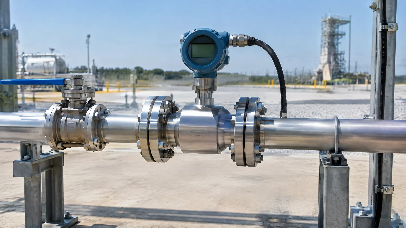
When a rocket-engine test report shows propellant flow, the number is not coming from a generic water-flow module or from pressure alone. A propellant flowmeter is an integrated flow instrument that measures flow rate in a test line and sends a traceable signal into the ground-test data system, while its sensing element and supporting instruments may be separate parts.
This article is part of the computer hardware technology guide library.
Key takeaways
A rocket propellant flow sensor is usually discussed more accurately as a flowmeter or flow-measurement instrument: it produces a flow-rate output for a defined fluid, range and installation.
In NASA Stennis examples, an axial turbine and magnetic pickup coil turn propellant movement into pulses that the acquisition system records and relates to volumetric flow.
Flow is not the same as pressure or tank level. A ground-test measurement system may use all three, but each answers a different question.
A flowmeter reading is conditional on the fluid, piping, instrumentation chain, data reduction and maintenance state. It is not a universal value that can be copied between test stands.
What does a rocket propellant flowmeter measure?
A propellant flowmeter measures the rate at which a propellant passes through a defined section of a test or supply line. Depending on the instrument and its calibration, the reported quantity may be volumetric flow rate, such as volume per unit time, or a related value used by the test system. The flowmeter does not, by itself, tell a reader the tank level, line pressure, fluid temperature or engine thrust.
NASA Stennis’ description of rocket-engine hot-fire instrumentation lists flow alongside pressure, differential pressure, temperature, thrust, position and other channels. That grouping is useful because it shows the flowmeter as one channel in a broader measurement system, not as a replacement for the other instruments.
The wording also matters. A sensor normally refers to the physical element that responds to a measurable effect. A flowmeter can include that element plus a pickup, signal conditioning, calibration information and a data-acquisition interface. In a rocket test report, the useful question is therefore: what flow quantity does the complete instrument output, under which stated conditions?
How a turbine-style flowmeter turns propellant movement into data
One flowmeter arrangement described by NASA Stennis uses an axial turbine in the line. As liquid passes through the meter, the turbine rotates. Magnets around the turbine pass an external induction sense coil, and each passage creates a pulse, sometimes described in the presentation as a ‘pip’. The test data system records the pulse rate, such as pulses per second, and the facility’s calibrated relationship converts that signal into a flow-rate result.
This is a signal chain rather than a single magical sensor reading: moving fluid creates rotor motion; the magnetic pickup converts motion into an electrical pulse; acquisition hardware records the pulse timing; and documented calibration information relates the output to flow. A different flowmeter technology can use a different physical effect and produce a different output.
The turbine and pickup are one example, not a specification for every launch vehicle or test stand. A flow instrument may be selected for its fluid compatibility, expected range, temperature and pressure environment, response, installation arrangement and maintenance needs. The reader should not infer that a small educational turbine sensor is suitable for cryogenic, high-pressure or propulsion service.
Flow versus pressure, level and thrust
Flow, pressure, level and thrust are related in a propulsion test, but they are different measurements. Flow describes movement through a line over time. Pressure describes force per unit area at a measurement point. Level describes the amount or position of liquid in a tank. Thrust describes the force produced by the tested engine or component. One channel cannot be substituted for another without a validated physical model and measurement relationship.
A ground facility may use tank-level or volume information as an independent check or as part of a flow determination. In the NASA Stennis example, changes between tank-volume switch points are used with flowmeter pulse data during facility calibration. That does not mean a tank level gauge is itself a flow sensor, or that every test stand uses the same arrangement.
Pressure and temperature instruments can also help interpret whether a flow measurement is plausible under the test condition. NASA’s launch-vehicle instrumentation guidance stresses that sensors and their wiring, connectors, installation and calibration considerations should be designed with the system they monitor. These supporting channels improve context; they do not change what the flowmeter physically senses.
| Measurement | Main question it answers | Why it is not interchangeable with flow |
|---|---|---|
| Flow rate | How much propellant passes a line section per unit time? | It depends on the flow instrument, fluid and calibration conditions. |
| Pressure | What pressure exists at a point or across a component? | Pressure difference can support an inferred flow calculation, but pressure alone is not a direct flow reading. |
| Tank level or volume | How much propellant is indicated in a tank? | A changing tank quantity can corroborate flow over time, but a level instrument is not the line flowmeter. |
| Thrust | What force does the engine or test article produce? | Thrust is a separate force measurement and cannot identify propellant flow by itself. |
Why the ground-test data system matters
The flowmeter’s electrical output is only useful when the complete instrumentation chain preserves its meaning. NASA Stennis describes wired measurements, signal-conditioning and data-acquisition systems with time-stamped channels. In practice, the logged record can include the flowmeter output alongside pressure, temperature, vibration, thrust and discrete events so engineers can compare channels at the same test time.
This does not make the result automatically accurate. Pulse counting, signal conditioning, timing, scaling, channel configuration and the calibration record all affect the reported engineering value. A displayed flow number may therefore be the end of data processing rather than a direct electrical quantity emitted by the sensing element.
For beginners, the safe mental model is a chain: physical flow, sensing element, electrical output, acquisition channel, calibration relationship and recorded flow value. If one link is misunderstood, the final number can be given more certainty than the instrument supports.
Important limitations in rocket-test flow measurement
A flowmeter is selected and qualified for an operating envelope. Fluid properties, temperature, pressure, contamination, corrosion, vibration, line geometry and transient behaviour can affect the measurement. A meter that is appropriate for a laboratory liquid demonstration is not automatically appropriate for a rocket test environment.
Moving-part meters also have wear and lifecycle considerations. NASA’s launch-vehicle lessons-learned material notes that flowmeters generally have less life capability than selected pressure and temperature transducers, while a meter without moving parts can have longer life in a low-contamination, low-corrosion environment. This is a general engineering observation, not a promise about any particular model.
NASA also highlights contamination control, drift, wiring, connector integrity, leakage and vibration-induced deterioration as instrumentation concerns. Those are reasons to treat flow data as a qualified measurement with records and checks, not as a number that can be trusted solely because it appears in a dashboard.
This article intentionally stays at the educational monitoring level. Real propulsion facilities require approved designs, compatible materials, formal calibration and verification, environmental qualification, operational controls and competent engineering teams. It should not be used as a feed-system, test-stand or propulsion-control procedure.
Frequently asked questions
The answers below keep the terms separate because flowmeter, pressure sensor and tank-level instrument are often confused in beginner discussions.
What is a rocket propellant flow sensor?
It is a sensing element or integrated flow instrument used to determine propellant flow rate in a defined line and condition. In a rocket ground-test system, the flowmeter output normally travels through signal conditioning and data acquisition before it becomes a recorded engineering value.
Is a propellant flowmeter the same as a pressure sensor?
No. A pressure sensor measures pressure at a point, while a flowmeter measures movement through a line. Pressure difference can be used in some flow-measurement methods, but a pressure reading alone is not automatically a flow reading.
How does a turbine rocket engine flowmeter work?
In the NASA Stennis example, liquid movement rotates an axial turbine. Magnets on the turbine pass an induction coil and produce pulses. The acquisition system records those pulses, and a documented flow relationship converts them into a volumetric flow result for the facility’s stated conditions.
Can a normal water flow sensor measure rocket propellant?
Not by default. Fluid compatibility, temperature, pressure, contamination control, materials, electrical requirements, installation and qualification all matter. A consumer or educational water-flow module should not be treated as suitable for a propulsion test merely because both applications involve moving liquid.
Why are flowmeters used in rocket engine ground tests?
They provide a time-varying flow measurement that can be examined with other test channels such as pressure, temperature, vibration and thrust. That helps a test team understand the run and compare measured behaviour with the test’s approved analysis and requirements.
About the image
AI-generated editorial illustration; not an actual product or mission photograph.
Source notes
Reporting record
techduopulse stores source destinations privately. Public notes remain non-clickable so every visitor journey stays on this website.
Source note: NASA Stennis Space Center rocket-engine hot-fire sensor presentation
Primary source · Rocket hot-fire instrumentation, axial-turbine facility flowmeter, magnetic pickup pulses, acquisition and flow-rate calibration contextSource note: NASA launch-vehicle instrumentation design and installation lesson
Primary source · Instrumentation integration, contamination, drift, vibration, lifecycle and verification considerationsRelated reading: techduopulse flow-sensor guide
Context source · General flow sensor versus flow meter terminology and broad measurement principlesNew application-focused explainer for rocket propellant flowmeters in civil launch-vehicle ground testing. Adds NASA Stennis evidence on axial-turbine flowmeters and pulse pickup within a hot-fire data system, distinguishes flow from pressure, level and thrust, and keeps calibration, propulsion-control and build guidance outside scope.


