SEO Title: Flow Sensor: Types, Working Principle and Uses Meta Description: Learn what a flow sensor measures, how liquid and gas sensors work, key types, accuracy limits, and flow-meter examples for Indian learners.
This article is part of the software engineering technologies guide library.
What is a flow sensor?
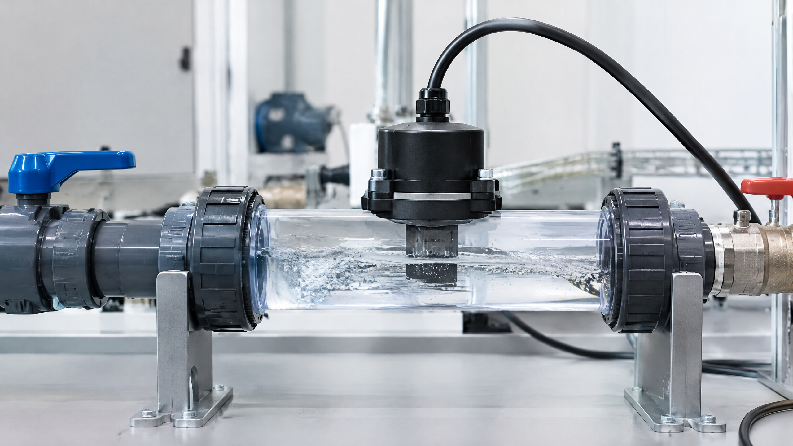
A flow sensor is a sensing element or transducer that detects a property associated with fluid in motion and produces a usable output. Depending on its design, the output can be pulses, a voltage, current, frequency or digital data. “Fluid” here includes both liquids and gases.
Flow is usually described in one of two ways:
Volumetric flow rate: volume passing a point in a time interval, such as L/min or m³/s.
Mass flow rate: mass passing a point in a time interval, such as kg/s.
The terms flow sensor and flow meter overlap in everyday use. A sensor may be the element that detects motion or a related effect; a complete flow meter may also include signal conditioning, calculation, calibration settings, a display and communications. So, a pulse-output water sensor can be part of a flow-meter system, but it is not automatically a calibrated, all-purpose industrial meter.
How does a flow sensor work?
The flow sensor working principle is a signal chain. Moving fluid changes something that can be measured, and electronics translate that change into a flow value. The changed property could be pressure, rotor speed, sound travel time, magnetic interaction or heat transfer.
A typical sequence looks like this:
Fluid moves through a pipe, channel or sensing path.
The flow changes a physical quantity, such as pressure difference or turbine rotation.
A sensing element converts that change into an electrical signal.
Electronics count, filter or condition the signal.
A controller, display or software estimates a flow rate after applying the appropriate calibration.
For example, an orifice or Venturi arrangement creates a pressure difference between two locations. Under the relevant operating conditions, that difference can be used to infer velocity and flow, but density, geometry and a discharge coefficient matter; it is not a universal one-to-one linear rule. [2] A turbine-style liquid flow sensor instead produces rotation or pulses related to flow only after calibration.
Main flow sensor types
The best type depends on whether the medium is liquid or gas, whether it conducts electricity, the pipe and installation, the desired flow range, and how much measurement uncertainty is acceptable. The following overview is deliberately broad; individual instruments can differ substantially.
| Type | What it senses | Typical fit and important boundary |
|---|---|---|
| Differential-pressure | Pressure difference across an orifice, Venturi or nozzle | Common measurement approach; fluid density, geometry and installation affect interpretation |
| Turbine/rotor | Rotor speed or pulse frequency | Often used for liquid-flow pulse outputs; viscosity, wear and particles can affect results |
| Ultrasonic | Sound transit time or Doppler shift | Can be non-intrusive; fluid, pipe, acoustic path and installation matter |
| Electromagnetic | Induced voltage in a flowing conductive liquid | Requires an electrically conductive liquid; it is not a general gas-flow method |
| Thermal-mass | Heat removed from a heated element | Often applied to gas flow; gas composition, temperature, pressure and placement can influence it |
| Coriolis | Motion of fluid through vibrating tubes | Targets mass flow; suitable instruments may also derive density and temperature |
### Differential-pressure flow measurement
Differential-pressure devices use a restriction or shaped section to create a pressure difference. Orifice plates, Venturi tubes and nozzles are familiar examples. The pressure readings alone are not the answer: the meter’s geometry, the fluid’s density and the applicable flow relationship must be accounted for. LibreTexts explains the Bernoulli-related basis and the trade-offs of orifice and Venturi measurement. [2]
### Turbine and rotor flow sensors
A moving liquid can turn a rotor. A pickup detects its rotational speed or generates pulses, which electronics convert into a flow estimate using a calibration factor. This makes the principle intuitive for an Arduino-style water-flow experiment, but a changing fluid viscosity, mechanical wear, particulate matter or unsuitable pipe installation can move the result away from the original calibration.
### Ultrasonic flow sensors
Ultrasonic flow measurement uses acoustic signals rather than a spinning part in the fluid path. Transit-time methods compare sound travel in upstream and downstream directions. Doppler methods rely on a frequency shift from scatterers in the fluid. Whether either approach is suitable depends on the liquid or gas, pipe material and shape, acoustic path and installation. Indian engineering teaching material describes ultrasonic measurement as a non-contact approach and also discusses hot-wire anemometry for air/liquid velocity contexts. [3]
### Electromagnetic, thermal and Coriolis methods
An electromagnetic flow meter uses electromagnetic induction and is intended for electrically conductive liquids. It should not be described as a general-purpose solution for measuring gas flow.
Thermal-mass sensing relates flow to the heat lost from a heated element, making it particularly relevant to some gas-flow applications. The gas composition, temperature, pressure and element placement may change the measurement response.
Coriolis instruments use the effect of moving fluid in vibrating tubes to target mass flow. Some suitable instruments can also derive density and temperature. That does not mean every device called a flow sensor measures mass flow directly.
Where flow measurement sensors are used
The same underlying idea appears in many everyday and industrial settings. In India, useful learning examples include:
Water systems: observing water movement in a pump line, tank-filling arrangement or irrigation experiment.
HVAC and building services: monitoring or controlling air or chilled-water movement where the selected instrument and installation suit the application.
Process instrumentation: measuring liquid, gas or utility flows in manufacturing and laboratory systems.
Environmental and engineering education: connecting a pulse-output sensor to a microcontroller to learn about interrupts, timing, units and calibration.
Automotive and machine systems: using purpose-built sensors where a system needs information about air, fuel, coolant or another fluid stream.
These examples explain possible uses, not a recommendation for a particular device or a promise of performance. Critical systems need an instrument selected, installed and maintained for their specific operating conditions.
Flow sensor vs flow meter: what is the difference?
A flow sensor is often the component that creates the signal. A flow meter is commonly the broader instrument or system that turns that signal into a reported value. In practice, suppliers and users may use the words interchangeably, so the more useful question is: what does this device output, what has been calibrated, and under which conditions?
For a student project, a module may provide pulse counts that code converts to L/min. For an industrial measurement loop, the complete meter may also provide conditioned output, diagnostics, configuration, a display and documented calibration. NIST’s flow-meter work highlights that meter principles and calibration conditions can vary with fluid, temperature, pressure, flow and installation. [1]
Accuracy, calibration and installation limits
A flow reading should be treated as a measurement with conditions, not as a universal fact. A sensor’s quoted capability, if supplied by its maker, is not necessarily the accuracy of the finished system.
Important sources of variation include:
Fluid properties: density and viscosity can change how a method responds; gas composition matters for thermal approaches.
Temperature and pressure: these can change the fluid and sensor response.
Installation geometry: bends, valves, reducers, obstructions and insufficient straight pipe can disturb the flow profile.
Pulsation and turbulence: a pump or compressor may create a changing flow that is harder to represent with one steady value.
Range and turndown: a device may be less useful when operated far from the conditions for which it was selected or calibrated.
Wear, fouling and particles: moving parts and sensing surfaces can change over time.
Signal handling: wiring, pulse counting, filtering, timing and software assumptions affect a microcontroller-based result.
Calibration compares an instrument’s output with a reference under defined conditions. It is most useful when those conditions resemble the actual application. NIST notes that flow-meter calibration and performance depend on conditions such as fluid, temperature, pressure, flow and installation, while ASME describes its flow-measurement performance test code as guidance for determining flow accurately with commonly used devices. [1] [4]
For a learning project, record the pipe size, fluid, test method and calibration conditions alongside the code. For a regulated, safety-critical or billing-related application, use the applicable standards, manufacturer documentation and competent engineering support rather than relying on a generic online explanation.
Practical notes for a water flow sensor and Arduino project
A small pulse-output water flow sensor can be a useful way to learn the water flow sensor working principle. Count pulses over a known time interval, convert the count with a calibration factor appropriate to that sensor and setup, then compare the estimate with a measured volume collected over the same interval. Repeat at more than one flow condition rather than assuming one factor works perfectly everywhere.
Keep the project scope realistic. The result may be adequate for observing changes or learning data acquisition, but it does not automatically establish suitability for potable water, high pressure, hazardous fluids, mains-connected equipment or any safety-critical purpose. Check the device documentation, electrical ratings, material compatibility and local requirements before installing anything in a live system.
FAQs
Flow sensor kya hai?
A flow sensor is a device or sensing element that converts a property of moving liquid or gas into an electrical signal. The system then uses that signal to estimate volumetric flow, mass flow or a related flow value after suitable calibration.
Flow sensor kaise kaam karta hai?
It detects an effect of movement—such as a pressure difference, spinning rotor, sound timing, induced voltage or heat loss—and converts that effect into pulses or another electrical output. Electronics and calibration turn that output into a displayed or logged flow estimate.
What is the water flow sensor working principle?
A water flow sensor may use a rotor that produces pulses, a pressure difference, sound waves, electromagnetic induction or another method. The exact principle matters because water conductivity, pipe layout, fluid cleanliness and calibration can affect whether a sensor is suitable and how its output is interpreted.
Can I use a water flow sensor with Arduino?
Yes, a pulse-output module can be used as an educational Arduino input when its electrical interface and supply requirements are understood. Count pulses accurately, use a documented or tested calibration factor for the setup, and treat the result as a project measurement rather than an automatic guarantee of real-world accuracy or safety.
What are the main flow sensor types in instrumentation?
Common types include differential-pressure, turbine/rotor, ultrasonic, electromagnetic, thermal-mass and Coriolis instruments. They do not measure in exactly the same way, and each has medium, installation and calibration constraints.
How does an ultrasonic flow sensor work?
A transit-time ultrasonic sensor compares sound travel with and against the flow direction. A Doppler version looks for a frequency shift from scatterers in the moving fluid. The pipe, acoustic path, fluid and installation influence whether the method will work well.
Flow meter vs flow sensor: which term is correct?
Both may be correct in context. “Flow sensor” often emphasises the signal-producing element, while “flow meter” can mean the complete calibrated instrument or measurement system. Check the device documentation to understand what it measures, outputs and claims under stated conditions.
Related reading
/article/pressure-sensor-working-principle-types
/article/ultrasonic-sensor-working-uses
/article/level-sensor-types-working-uses
/article/gas-sensor-working-principle-types
/article/temperature-sensor-types-working-principle
Source notes
Reporting record
techduopulse stores source destinations privately. Public notes remain non-clickable so every visitor journey stays on this website.
https://support.google.com/trends/answer/4365533?hl=en
Primary source · Research source 6https://developers.google.com/search/docs/monitor-debug/trends-start
Primary source · Research source 5https://www.nist.gov/programs-projects/understanding-flow-meters
Primary source · Research source 1https://eng.libretexts.org/Bookshelves/Industrial_and_Systems_Engineering/Chemical_Process_Dynamics_and_Controls_(Woolf
Primary source · Research source 2https://www.saranathan.ac.in/attachments/eresources/ece/R2017/OIC751.pdf
Primary source · Research source 3https://www.asme.org/codes-standards/find-codes-standards/flow-measurement
Primary source · Research source 4New India-focused sensor explainer covering flow sensor, working principles, uses and limitations.