
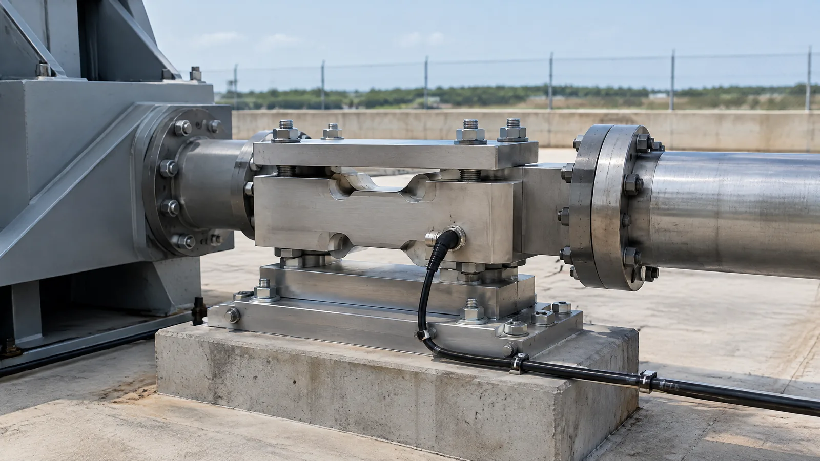
When a rocket engine fires on a ground-test stand, engineers need to know whether the stand is measuring engine force or merely recording a nearby pressure, vibration or flow signal. A rocket engine thrust sensor is usually a load cell or dynamometer arranged in the stand’s force path; it measures reaction force, which the test system records and relates to thrust.
This article is part of the computer hardware technology guide library.
Key takeaways
A thrust load cell or dynamometer is a force-measurement instrument used on a ground test stand, not a sensor fitted inside a nozzle.
The physical instrument, its mounting and force path, signal conditioning, data acquisition and calibration together make the measurement system.
Six-axis, piezoelectric and other designs are application-specific options. They should not be treated as universal requirements.
Pressure, vibration, temperature and flow instruments provide related test data, but they do not replace the thrust measurement channel.
What is a rocket engine thrust sensor?
A rocket engine thrust sensor measures the mechanical reaction force produced when an engine operates against a test stand. In this application, the sensor is commonly described as a thrust load cell, force transducer or dynamometer. The word “thrust” describes the engineering quantity of interest; the instrument itself is measuring force through the stand’s designed load path.
Kistler’s rocket-engine testing guidance describes application-specific dynamometers, including six-axis piezoelectric dynamometers, for thrust investigations. That wording matters: a dynamometer is an integrated force-measurement arrangement, and its construction depends on the stand, expected loads, dynamics and measurement objective. A general load cell from a weighing project is not automatically suitable for a rocket test stand.
The sensor also should not be confused with a pressure transducer in the combustion chamber, an accelerometer on the structure or a flowmeter in the propellant system. Those instruments can help explain engine behaviour, but they measure different physical quantities.
How does a thrust load cell fit into a test stand?
The useful result comes from a chain rather than from the sensor body alone. Engine force is transferred through the stand’s intended mechanical path. The load cell or dynamometer responds to that force, its electrical output is conditioned, and a data-acquisition system records and scales the signal for engineering analysis.
NASA Stennis’ presentation on typical rocket-engine hot-fire sensors lists thrust among the measurements handled by its low-speed data-acquisition system. The same system also handles temperature, pressure, differential pressure, flow, position and related channels. This illustrates why a thrust reading is part of a coordinated test-instrumentation setup rather than a standalone number on a display.
The acquisition system and its timing matter when readings from different channels need to be compared. In the NASA Stennis example, measurements are wired and time-stamped with IRIG time. Its stated facility figures—250 samples per second for the low-speed system and 102,400 samples per second for the high-speed system—are examples of that facility, not universal specifications for every test stand.
- Physical sensor: the load cell or dynamometer that responds to force.
- Mechanical structure: the test stand, fixtures and intended load path that transfer force to the sensor.
- Signal chain: excitation or charge handling, amplification, filtering and analogue-to-digital conversion as required by the sensor design.
- Data system: acquisition, time alignment, scaling and recording of the channel.
- Calibration reference: the process and documentation used to relate output to a known force under the relevant setup.
Dynamometer, load cell and force sensor: what is the difference?
A force sensor is the broad category. A load cell is a force sensor intended to measure load in a defined arrangement. A dynamometer is a more application-oriented force-measurement instrument or assembly, often chosen when the test requires a particular geometry, multiple force components or dynamic response.
In a rocket test stand, the term dynamometer can therefore refer to more than a small sensing element. Kistler describes single- and multicomponent force sensors combined into application-specific dynamometers or force plates. A six-axis design can measure multiple components when the application calls for it, but that does not mean every stand needs six-axis measurement.
Piezoelectric force sensors are also not the only possible technology. Their suitability depends on the required static or dynamic behaviour, temperature environment, natural frequency, mounting and readout. Select the instrument from the complete test requirement and supplier documentation, not from the name “rocket thrust sensor” alone.
- Load cell: a force-sensing element or transducer used in a defined load path.
- Dynamometer: an integrated or application-specific force-measurement arrangement, potentially with multiple components.
- Rocket engine thrust sensor: an application description for the force-measurement channel used to determine engine thrust on a test stand.
Which instruments are optional or separate from the thrust sensor?
A ground-test campaign may use several instruments at once, but they should not be merged conceptually. NASA Stennis lists thermocouples and RTDs for temperature, pressure transducers and transmitters for pressure, accelerometers and strain gauges for structural or dynamic measurements, and flow instrumentation for propellant systems. Kistler likewise discusses thrust, pressure and vibration as separate measurement areas.
The exact combination is model- and facility-specific. A test may add a high-speed accelerometer to examine vibration or turbopump health, for example, but the accelerometer is not an alternate thrust load cell. A pressure sensor can show combustion or feed-system behaviour, but pressure alone is not a direct measurement of the stand reaction force.
External signal conditioning, cabling, a data-acquisition unit and calibration equipment may be essential to the completed measurement system without being part of the physical dynamometer. This distinction helps readers interpret equipment lists accurately and avoids assuming that one sensor package does every job.
| Measurement goal | Typical instrument family | What it does not directly measure |
|---|---|---|
| Engine reaction force | Thrust load cell or dynamometer | Chamber pressure or propellant flow |
| Combustion or feed pressure | Pressure transducer or transmitter | Stand reaction force |
| Structural motion and vibration | Accelerometer or strain gauge | Calibrated engine thrust by itself |
| Propellant movement | Flowmeter | Mechanical thrust force |
Limitations and responsible interpretation
A thrust sensor reading is only as meaningful as the force path, mounting and calibration behind it. Misalignment, unintended loads, vibration, temperature effects, sensor overload, electrical noise or incorrect scaling can affect the result. The supplied technical sources support treating the sensor and acquisition chain as a system; they do not provide a universal uncertainty value for all rocket stands.
Do not copy a load-cell rating or wiring arrangement from a hobby project into a propulsion test environment. A real test stand needs qualified mechanical, electrical and safety engineering, documented procedures and equipment selected for its environment. This article explains the measurement concept only; it is not a build guide, test protocol or certification of any component.
The safest plain-English interpretation is: the dynamometer gives the test system a force channel, while the other sensors provide context for understanding what happened during the run. Engineers compare those synchronized channels with the stand’s calibration and instrumentation records before drawing conclusions about engine performance.
Rocket engine thrust sensor FAQs
These answers use the supplied Kistler and NASA Stennis technical material and keep facility-specific details separate from general concepts.
Is a rocket engine thrust sensor the same as a load cell?
It can be a load cell or another force transducer selected for the test stand. “Rocket engine thrust sensor” describes the application, while “load cell” names a common force-sensing instrument. A dynamometer may integrate one or more force components for a specific stand.
Does a thrust dynamometer measure chamber pressure?
No. A thrust dynamometer measures force in the stand’s intended load path. Chamber or feed pressure requires a separate pressure transducer, although both channels may be recorded during the same test.
Are six-axis piezoelectric dynamometers required for every rocket test?
No. Kistler describes six-axis piezoelectric dynamometers as application-specific options for thrust investigations. The appropriate number of axes and sensing technology depends on the stand, expected loads and measurement objectives.
Why does the data-acquisition system matter?
The sensor output must be conditioned, digitised, timed and scaled before it becomes a useful engineering record. NASA Stennis describes thrust as one channel among several in its hot-fire data-acquisition systems, with facility-specific sampling and timing arrangements.
About the image
AI-generated editorial illustration; not an actual product or mission photograph.
Source notes
Reporting record
techduopulse stores source destinations privately. Public notes remain non-clickable so every visitor journey stays on this website.
Related reading: techduopulse force-sensor guide
Context source · Existing broad guide; used to distinguish this rocket-test-stand application page from duplicate coverageSource note: Kistler rocket-engine testing measurement guidance
Primary source · Thrust characterization, application-specific dynamometers, force measurement and separate pressure/vibration channelsSource note: NASA Stennis rocket hot-fire sensor and facility flowmeter-calibration presentation
Primary source · Thrust in low-speed acquisition, separate sensor families, facility-specific sampling and time-stamped wired measurementsNew distinct application article for rocket engine thrust measurement on a ground-test stand. It separates the physical load cell/dynamometer from the mechanical stand, signal chain, data acquisition and calibration context; distinguishes optional/model-specific six-axis and piezoelectric designs from universal requirements; and avoids propulsion construction, test protocols, safety certification, unsupported uncertainty claims and rankings.


