
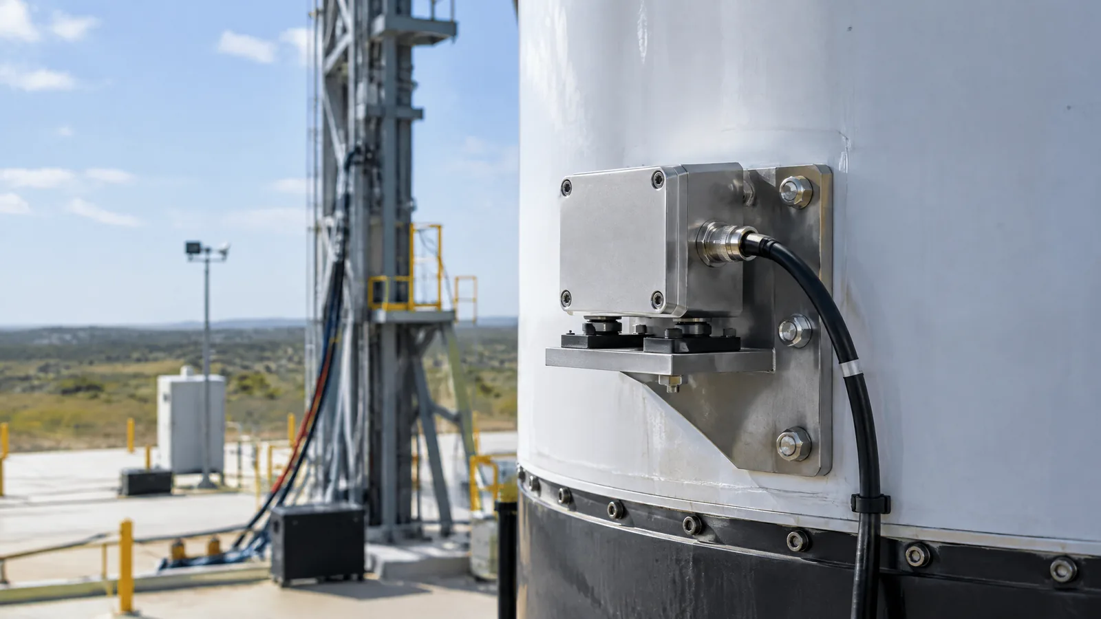
When a launch vehicle leaves the pad, its avionics need a measurement of changing motion rather than a camera view of the outside world. A rocket accelerometer sensor measures linear acceleration along its sensing axes; that data may support an inertial measurement unit and onboard navigation, while a separately mounted test sensor may record how the vehicle structure experienced flight.
This article is part of the computer hardware technology guide library.
Key takeaways
- An accelerometer measures linear acceleration, not speed, position, or rotation by itself.
- In a rocket avionics system, accelerometer data can be one input to an IMU and an onboard navigation chain.
- An IMU is a larger instrument that combines sensor types; it is not the same as one accelerometer transducer.
- Development flight instrumentation may use separate accelerometers to observe vehicle-level vibration or motion during testing.
- Axes, range, bandwidth, mounting, temperature behaviour, calibration and redundancy depend on the vehicle design.
What does a rocket accelerometer sensor measure?
A rocket accelerometer sensor measures linear acceleration: the change in velocity along one or more defined axes. Its output is an acceleration signal, commonly represented in metres per second squared or in a gravitational-acceleration unit. It does not directly report altitude, ground speed, position or attitude.
The word linear describes translation along an axis, not the absence of rotation elsewhere in the vehicle. A launch vehicle can translate and rotate at the same time, so an accelerometer is normally one part of a broader motion-sensing arrangement. The sensor’s X, Y and Z labels belong to its installation and coordinate definition; they are not automatically north, east and up.
The reading also needs context. A sensor responds to the forces and motion seen at its mounting location, and real systems account for bias, noise, cross-axis effects and environmental conditions. The exact error budget and correction process are vehicle-specific rather than properties that can be assumed from the word accelerometer alone.
How the sensor fits into rocket avionics
Inertial sensing starts with transducers that turn physical motion into electrical signals. Safran describes an inertial measurement unit, or IMU, as a device combining accelerometers and gyroscopes to measure linear acceleration and angular velocity. The IMU supplies raw motion data to systems that calculate movement and orientation in real time. [Source note: Safran inertial measurement unit guidance]
That distinction matters: the accelerometer is the sensing element or instrument channel, while the IMU is an integrated package and the navigation system is the larger processing function. A rocket may use additional sensors and software to estimate its state. This article does not describe guidance algorithms or tell readers how to implement them, because those details depend on the vehicle, mission and safety-critical engineering process.
An inertial sensor can be useful when an external positioning signal is unavailable, but ‘works without GPS’ should not be read as ‘needs no other information’. Drift, calibration, alignment, timing and system modelling still affect the result. Safran’s general IMU explanation supports the role of raw acceleration and angular-rate data, not a universal performance promise for every launch vehicle.
Navigation accelerometer versus flight-test accelerometer
Two accelerometers on or around a launch vehicle can serve different engineering purposes. A navigation-related sensor is part of the operational avionics measurement chain. A development-flight-instrumentation sensor is installed to collect evidence about vehicle behaviour, such as acceleration or vibration, so engineers can compare flight data with models and investigate uncertainties.
NASA’s launch-vehicle instrumentation paper describes Development Flight Instrumentation, or DFI, as a vehicle-level system for testing performance models. It lists acceleration among typical measurements and explains that sensors convert physical phenomena into electrical signals read by data-acquisition units. [Source note: NASA Design Considerations for a Launch Vehicle Development Flight Instrumentation System]
NASA also separates DFI hardware from the operational flight resources in its discussion. A DFI setup can include sensors, signal conditioning, acquisition units, telemetry, recorders, harnesses and mounting provisions, but the exact combination varies. Therefore, a structurally mounted test accelerometer is not automatically the sensor used for navigation, and a navigation IMU should not be described as a complete flight-test recorder.
Why mounting and the signal chain matter
The number printed by an accelerometer is meaningful only with its installation and data path understood. NASA notes that launch-vehicle instrumentation components need mounting schemes suited to their environmental requirements and that sensors may be mounted in bosses or inserts. Mounting location can change which local vibration and structural motion the instrument sees. [Source note: NASA launch-vehicle development-flight-instrumentation design paper]
The signal chain can include the sensor, conditioning electronics, analogue-to-digital conversion, a data-acquisition unit, timing, telemetry and onboard recording. NASA highlights timing, buffering and synchronisation as important for later analysis. A clean-looking plot can still be misleading if its axis definition, sample timing, filtering or mounting reference is unknown.
For the same reason, specifications should be read as a matched set. Engineers choose an acceleration range and bandwidth that fit the measurement, then evaluate noise, bias stability, temperature response, shock and vibration tolerance, alignment, power and data rate. A catalogue value from one IMU or accelerometer cannot be transferred to an unnamed rocket.
What this sensor cannot tell you by itself
An accelerometer alone cannot identify a vehicle’s complete position or orientation. It does not measure angular velocity in the way a gyroscope does, and it does not replace navigation software, timing references or other vehicle sensors. Integrating acceleration to estimate velocity and position also makes calibration and drift important engineering concerns.
It is also unsafe to infer launch success, structural health or control performance from one public graph or one sensor channel. Civil launch vehicles use system-level design, verification and analysis. For readers learning the vocabulary, the practical rule is simple: ask which physical quantity was measured, where the instrument was mounted, how the signal was conditioned, and whether the channel belonged to operational avionics or development testing.
Frequently asked questions
Is a rocket accelerometer the same as an IMU?
No. An accelerometer measures linear acceleration. An IMU is an integrated instrument that combines accelerometers with gyroscopes and may include other sensing elements, electronics and interfaces.
Why does a launch vehicle need acceleration data?
Acceleration data can provide raw motion information to an inertial measurement and navigation chain. The exact role, processing and redundancy are specific to the vehicle and mission.
What is a flight-test accelerometer used for?
A development-flight-instrumentation accelerometer can record vehicle-level acceleration or vibration so engineers can compare measured behaviour with models. It may be separate from the operational navigation instrument.
Does an accelerometer measure rocket speed?
Not directly. It measures acceleration. Speed or velocity can be estimated by processing acceleration over time, but that estimate depends on alignment, timing, calibration, drift and other system information.
Are all rocket accelerometers identical?
No. Axis count, range, bandwidth, noise, environmental qualification, mounting, data interface and redundancy vary by application. A public description should not assume a particular model or specification without evidence.
About the image
AI-generated editorial illustration; not an actual product or mission photograph.
Source notes
Reporting record
techduopulse stores source destinations privately. Public notes remain non-clickable so every visitor journey stays on this website.
Source note: Safran inertial measurement unit guidance
Primary source · IMU combines accelerometers and gyroscopes; raw linear-acceleration and angular-rate data supports onboard motion calculationsSource note: NASA launch-vehicle development-flight-instrumentation design paper
Primary source · DFI purpose, acceleration sensors, data acquisition, mounting provisions, and timing/synchronisation considerationsInitial 15 October 2026 distinct application article. Separates the broad accelerometer guide from launch-vehicle avionics, distinguishes an accelerometer from an IMU and navigation system, and distinguishes operational navigation sensing from NASA-described development flight instrumentation without assigning model-specific specifications or guidance details.


