
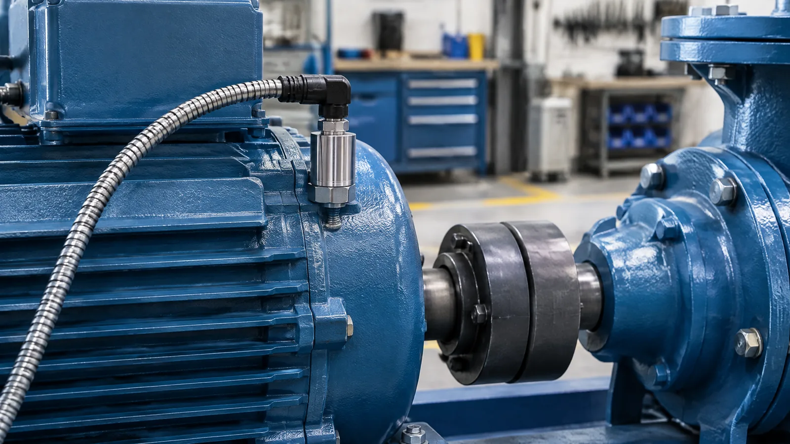
A pump or motor can keep running while its vibration pattern slowly changes, leaving a maintenance team to decide whether a new reading is meaningful or just measurement noise. An industrial vibration sensor measures mechanical vibration—typically through an accelerometer and evaluation electronics—so teams can trend amplitude, frequency or related values before a suspected problem becomes a stoppage.
This article is part of the computer hardware technology guide library.
Key takeaways
Industrial vibration sensor monitoring is a condition-monitoring method, not an automatic fault diagnosis. The useful result comes from the complete setup: a physical sensing element, signal conditioning or evaluation electronics, a suitable instrument or gateway, and analysis against the machine’s own operating history.
- An accelerometer converts machine motion into an electrical signal; the rest of the system turns that signal into a value or trend.
- Amplitude and frequency can change when machine conditions change, but the same reading does not mean the same thing on every asset.
- Mounting, bandwidth, noise, temperature, speed and load affect what the sensor can show.
- A normal baseline and qualified maintenance review are needed before acting on an alert.
What does an industrial vibration sensor measure?
An industrial vibration sensor measures oscillatory motion in or around equipment such as a fan, pump, motor, gearbox or conveyor. The physical sensor is commonly an accelerometer. Its output can represent acceleration, while an integrated device may calculate another condition indicator such as overall vibration or RMS velocity. The exact output depends on the model and its electronics, so the label “vibration sensor” is not one universal specification. [1]
A monitoring system may collect a time waveform, an overall value, a frequency spectrum, or a trend over repeated readings. Amplitude describes how strong the vibration is in the selected measurement, while frequency helps show how that vibration is distributed across rates of repetition. These signals can help a team notice a change from normal operation; they do not identify a failed bearing or misaligned shaft from one raw number alone. [1] [2]
The sensor itself is not the whole monitoring system. A physical accelerometer detects motion, evaluation electronics condition or calculate the signal, and an instrument, PLC, wireless gateway or software platform stores and interprets the result. A product may combine several of these functions in one housing, but optional gateways, cables, data-acquisition hardware and analytics software should not be assumed to be included in every installation.
How machine condition monitoring uses the signal
Condition monitoring compares measurements taken under defined operating conditions with a useful reference. For example, a maintenance team might trend a pump’s vibration while recording speed, load and measurement location. A gradual change, a new frequency component or an unusual event can justify a closer inspection. Research reviews describe vibration data as information about oscillation, amplitude and frequency, with accelerometers widely used to convert machine vibration into electrical signals for analysis. [2]
The first reference should be the machine’s own normal behaviour. Different machines, mounting points and operating speeds produce different vibration patterns, so a threshold copied from another asset can create missed warnings or false alarms. Establishing a baseline takes repeated observations and context. Temperature, humidity, nearby machinery and changing process conditions can also interfere with interpretation. [2]
This is why “predictive maintenance” should be read as a workflow rather than a promise made by a sensor. A sensor can supply evidence for a maintenance decision, but diagnosis usually requires trend review, operating context, inspection and, where appropriate, other measurements such as temperature or speed.
- Define the asset and measurement point.
- Record operating speed, load and relevant process conditions.
- Collect comparable readings to establish normal behaviour.
- Review a change with maintenance personnel before scheduling work or declaring a fault.
Choosing the sensor and signal path
Selection starts with the machine and the vibration you need to observe, not with a generic sensor label. TE Connectivity identifies frequency response, measurement resolution and dynamic range, long-term drift, operating temperature, packaging, installation and output options as important condition-monitoring factors. Noise, electromagnetic interference, the data-acquisition interface and cable length can also affect the usable measurement. [3]
Piezoelectric and MEMS variable-capacitance accelerometers are different sensing technologies with different trade-offs. Piezoelectric devices can suit applications needing broad frequency response and dynamic range, while MEMS devices can provide compact packaging and a response that includes very low frequencies or DC, depending on the design. The source comparison is a technical discussion of particular device classes, not a reason to call one technology best for every fan, pump or motor. [3]
Check the data sheet for measurement axes, range, frequency response, sensitivity, output type, temperature limits, ingress protection and power requirements. A single-axis sensor may suit a known measurement direction; a triaxial sensor can capture three directions but adds data and interpretation requirements. Analog voltage, 4–20 mA, IO-Link, CAN or wireless output describe the signal path, not the physical vibration quantity by themselves. [1] [3]
| Part of the setup | What it does | Why it matters |
|---|---|---|
| Accelerometer | Senses motion along one or more axes | The axis and range must suit the machine and location |
| Evaluation electronics | Conditions the signal or calculates a vibration value | Filtering and calculation affect the reported result |
| Instrument, PLC or gateway | Powers, receives or forwards data | Interface, cable length and wireless conditions affect collection |
| Software and maintenance process | Stores trends and compares them with context | A trend needs a baseline and qualified interpretation |
Why mounting changes the reading
The way a sensor is attached becomes part of the measurement. Wilcoxon describes stud mounting, adhesive mounting, magnetic mounting and probe tips as common methods, with mounting stiffness controlling the mounted sensor’s frequency response. A rigid, well-prepared permanent mount generally transfers vibration more consistently than a loose or temporary contact. [4]
Stud mounting is commonly used for permanent installations and high-frequency work. Adhesive mounting can be a practical alternative where drilling is not allowed, but surface preparation and adhesive choice matter. Magnetic mounts are useful for temporary route-based checks, yet their added mass and contact can reduce the usable frequency range. Probe tips are convenient in difficult locations but are more prone to poor contact and distorted spectral data. [4]
The mounting method should be recorded with the measurement. Moving a magnetic sensor to a different spot, changing the contact surface or measuring while the machine is at a different speed can make two readings look different even when the machine has not developed a new fault.
- Use a defined measurement point and orientation.
- Prepare the surface as required by the selected mount.
- Keep the mounting method consistent when comparing trends.
- Treat a changed installation as a change in the measurement setup, not automatically as a machine event.
Limits and safe interpretation
An industrial vibration sensor can reveal a change in machine behaviour, but it cannot guarantee that a machine is healthy or name the failed component on its own. Poor placement, unsuitable bandwidth, sensor drift, electrical interference, temperature changes and neighbouring vibration can all affect the result. A high reading may need confirmation; a normal reading may not rule out every issue. [2] [3]
Avoid treating a universal alarm value as valid for every asset. The acceptable range depends on the machine design, speed, mounting point, operating state, sensor specification and the chosen measurement quantity. Use manufacturer and site procedures, applicable standards and trained personnel for real maintenance decisions. Do not use a hobby sensor or an isolated dashboard reading as a safety interlock for people, rotating equipment or building systems.
Frequently asked questions
Is an industrial vibration sensor the same as an accelerometer?
Not always. An accelerometer is the physical sensing element commonly used to detect machine vibration. An industrial vibration sensor may combine that accelerometer with signal conditioning, evaluation electronics, a transmitter or a monitoring interface. [1]
Can vibration monitoring predict a motor failure?
It can provide evidence of a change that deserves investigation, but one reading does not predict or diagnose every failure. Reliable interpretation needs a machine-specific baseline, comparable operating conditions and maintenance review. [2]
Is a wireless vibration sensor always better?
No. Wireless delivery can simplify installation in some locations, while wired or loop-powered outputs may fit other plant systems. The choice depends on access, power, distance, data rate, environment and the monitoring purpose.
Why does sensor mounting matter?
The mount affects how vibration reaches the sensing element and therefore changes frequency response. Stud and suitable adhesive mounts are commonly used for permanent measurements; magnets and probe tips have more limitations. [4]
About the image
AI-generated editorial illustration; not an actual product or mission photograph.
Source notes
Reporting record
techduopulse stores source destinations privately. Public notes remain non-clickable so every visitor journey stays on this website.
Source note: ifm vibration sensors and transmitters application guidance
Primary source · What industrial vibration sensors measure; integrated accelerometer and evaluation electronics; model-specific ranges and outputsSource note: peer-reviewed review of vibration-based condition monitoring
Primary source · Vibration data, accelerometer use, baselines, environmental interference, placement and interpretation limitsSource note: TE Connectivity Sensors vibration condition-monitoring white paper
Primary source · Frequency response, resolution, drift, temperature, output options and piezoelectric versus MEMS technologySource note: Wilcoxon sensor mounting guidance
Primary source · Stud, adhesive, magnetic and probe mounting; surface preparation and frequency-response effectsNew India-focused application explainer distinct from the existing general accelerometer guide. It explains industrial vibration sensor monitoring for fans, pumps and motors; separates the physical accelerometer, evaluation electronics, instruments, gateways and software; and qualifies baselines, mounting, bandwidth, model-specific outputs and maintenance interpretation without promising automatic diagnosis.


