
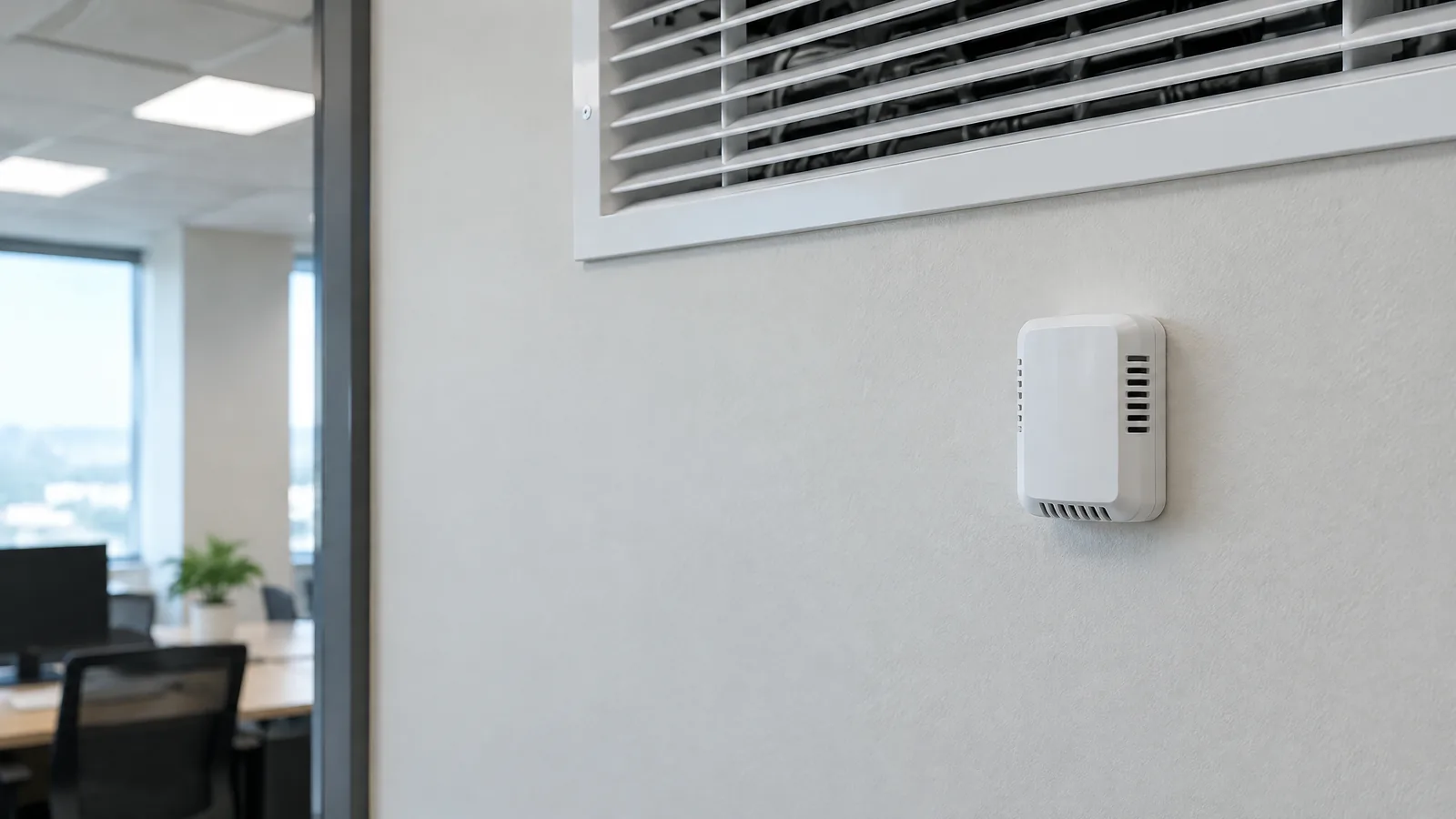
A room feels unevenly cooled, yet the building dashboard shows a normal number—this is often a measurement and placement question before it is a controller question. An HVAC zone temperature sensor measures the temperature at a selected room or air location, such as a zone, supply-air path or return-air path, so a building automation system can observe conditions and make informed control or review decisions.
This article is part of the computer hardware technology guide library.
What an HVAC zone temperature sensor measures
An HVAC zone temperature sensor is a temperature probe or sensing element installed at a chosen point in a building system. In a room, it reports the local air temperature near the sensor. In ductwork or equipment, a probe can measure supply-air or return-air temperature. These are different measurement points, so their readings should not be treated as interchangeable.
The sensor itself is not the thermostat, controller or building automation system. The physical element responds to temperature; optional signal-conditioning electronics may excite, amplify, filter or convert its signal; a controller or gateway may then transmit the value; and BAS software may display it, compare it with other data or use it as one input to a control sequence. A packaged wall device can contain several of these functions, but the roles remain distinct.
NIST’s smart-building blueprint describes temperature as one kind of interior and exterior building data used to support operations, energy work and occupant comfort. That makes the HVAC temperature sensor an observation point in a larger system, not a complete description of every condition in a room.
- Zone or room sensor: samples air near an occupied area, subject to local airflow, sunlight, walls and nearby heat sources.
- Supply-air sensor: samples air leaving an air-handling or terminal unit before it mixes through the space.
- Return-air sensor: samples air coming back toward equipment and can describe a mixed return path rather than a particular occupant’s location.
How the measurement travels into an HVAC system
The measurement path normally begins with heat reaching the sensing element. Its electrical property then changes: an RTD changes resistance, an NTC thermistor generally decreases in resistance as temperature rises, and a thermocouple produces a small voltage from two dissimilar metals. A semiconductor or digital sensor can provide an analogue or digital output from an integrated sensing element.
The selected sensor family is only one part of the result. A controller or input module must provide the appropriate excitation, reference, conversion and signal handling. NI notes that RTD readings can be influenced by lead-wire resistance, thermocouples need suitable reference-junction compensation, and thermistors can be affected by self-heating. In a building installation, cable routing, electrical noise, enclosure design and the interface’s specifications also matter.
A network gateway, wireless node or BAS server may be present, but these are optional external components rather than the physical temperature sensor. They can move or display data; they do not automatically improve a poorly placed probe or turn one local reading into a whole-zone average.
- Physical sensor or probe: responds to the air or surface at its installed point.
- Optional interface or transmitter: conditions the signal or presents a standard input to a controller.
- Controller and BAS: interpret the value alongside schedules, occupancy, airflow and other system inputs.
Placement determines what the number means
A zone sensor should be located and protected according to the system design, because the nearest air pocket is not always representative of the occupied zone. Direct sun, exterior walls, doors, supply-air discharge, return grilles, equipment heat and crowded enclosures can bias a local reading. A sensor hidden inside a warm electrical box may report its enclosure rather than the room.
Supply-air and return-air points answer different questions. Supply air helps describe what the equipment or terminal is delivering at that point. Return air can describe mixed air heading back to equipment. Neither one alone proves that every occupied corner has the same temperature. NIST’s blueprint connects sensor data with performance monitoring and fault detection, but those uses depend on the quality, location and context of the installed data.
Calibration and response time also matter. A probe with a protective sheath may withstand the environment while responding more slowly. A reading that changes quickly is not automatically more accurate, and a stable display is not proof that the room is uniform. The appropriate reference, interval and documentation should come from the equipment and measurement requirements rather than an assumed offset.
What HVAC temperature sensors can and cannot tell you
A correctly selected sensor can provide a useful local temperature input for comfort monitoring, control sequences and unusual-condition review. Multiple points can help an operator compare zones, supply air and return air over time. BAS analytics may use these values with other signals to identify a possible fault or inefficiency, as the NIST blueprint describes.
The sensor cannot by itself diagnose poor ventilation, guarantee thermal comfort, prove equipment safety or identify the cause of every complaint. Temperature is only one variable. Air movement, humidity, radiant surfaces, occupancy, system schedules and sensor location can all affect how a space is experienced. A single point also cannot establish conditions in unmeasured rooms.
Avoid treating a hobby module, an unverified wireless node or a generic probe as automatically suitable for a commercial HVAC installation. The enclosure, operating range, mounting method, wiring, communications path and controller compatibility should match the system specification. Work on installed building controls should follow the responsible facility team and applicable equipment instructions; this article is not a wiring or control-override procedure.
| Question | What the sensor can contribute | What still needs other evidence |
|---|---|---|
| Is a local zone warmer or cooler than expected? | A reading at the selected sensor point | Whether the point represents the whole occupied area |
| Is air leaving or returning at an unusual temperature? | A supply-air or return-air measurement at the installed point | The equipment fault or the cause of the difference |
| Can a BAS monitor a condition over time? | A time-stamped input when the system is designed and configured for it | Correct interpretation, calibration and an appropriate response |
Choosing a sensor family for a building installation
There is no universal best HVAC temperature sensor. RTDs are often considered when stability, repeatability and relatively linear response are priorities, but lead resistance and interface requirements must be addressed. NTC thermistors can be sensitive over a more limited range and may be practical for suitable room-temperature measurements, while self-heating and nonlinearity require attention. Thermocouples offer broad temperature capability and rugged forms, but their small nonlinear signal and reference-junction requirements make the complete interface important. IC or digital sensors can simplify compact electronics, but their limits remain component-specific.
Select against the actual target and conditions: room air, supply air, return air or a surface; expected temperature range; moisture and contamination; airflow; cable length; electrical environment; response needs; mounting; and the input format accepted by the controller. The sensor, probe housing, transmitter and controller are a measurement chain, so comparing only a headline accuracy number can be misleading.
- Define the point being measured before choosing the sensor package.
- Check the full rated range and environmental requirements for the installed location.
- Confirm the input and signal-conditioning method with the responsible system designer.
- Review placement and calibration records before interpreting a surprising value.
Key takeaways
An HVAC zone temperature sensor measures temperature at a selected room, supply-air or return-air point. It is a physical measurement input, not the whole thermostat or BAS.
Placement, thermal contact, airflow, wiring, calibration and response time shape the usefulness of the reading.
Optional interfaces, transmitters, gateways and BAS software process or transport the signal but do not replace the sensor’s physical measurement.
Use the value with other building evidence; one local temperature reading cannot prove comfort, ventilation or equipment safety across an entire building.
Frequently asked questions
Is an HVAC zone temperature sensor the same as a thermostat?
No. The sensor measures temperature at a chosen point. A thermostat may combine sensing, user settings, logic and control outputs, while a BAS can use sensor data as one input among many. Product packaging can combine these roles, but the functions are different.
What is the difference between a zone, supply-air and return-air temperature sensor?
A zone sensor measures near an occupied area, a supply-air sensor measures air delivered from equipment or a terminal, and a return-air sensor measures air moving back toward equipment. Their locations and purposes are different, so their readings should not be substituted casually.
Why might an HVAC temperature sensor show a value that feels wrong?
The sensor may be affected by sunlight, a nearby wall, a supply outlet, a return grille, equipment heat, enclosure heat, airflow or poor thermal contact. Calibration, wiring and the selected measurement point can also affect the displayed value.
Can one HVAC temperature sensor represent a whole room or building?
It represents the conditions at its installed point. It may be a useful zone input when the location and system design support that use, but one sensor cannot establish temperature everywhere or explain every comfort complaint.
About the image
AI-generated editorial illustration; not an actual product or mission photograph.
Source notes
Reporting record
techduopulse stores source destinations privately. Public notes remain non-clickable so every visitor journey stays on this website.
Source note: National Instruments temperature measurement fundamentals
Primary source · Sensor-family mechanisms, lead resistance, self-heating, response time, mounting and selection criteriaSource note: Texas Instruments temperature-sensing technical reference
Primary source · Thermocouple, RTD, thermistor and IC sensing principles; interface and component distinctionsSource note: NIST Smart Buildings blueprint
Primary source · Temperature as smart-building data; BAS; real-time temperature sensing; HVAC performance monitoring and fault detectionSource note: NIST temperature units
Primary source · Celsius and kelvin relationshipNew application page for HVAC zone temperature sensors, distinct from the existing generic temperature-sensor guide. Explains room, supply-air and return-air measurement points; separates physical probes from optional interfaces, gateways, controllers and BAS software; and qualifies placement, calibration, sensor-family and interpretation limits without giving unsafe control or wiring instructions.


