
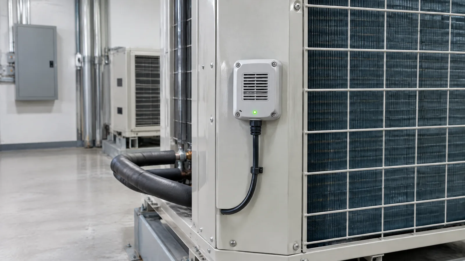
A cooling plant can keep running while a small refrigerant loss goes unnoticed, leaving a facilities team to investigate rising service calls, poor cooling or an unexpected alarm. An HVAC refrigerant-leak detection system measures the presence or concentration of a specified refrigerant near equipment and turns that signal into an alert or recorded event; it does not, by itself, locate, repair or safely recharge a leak.
This article is part of the computer hardware technology guide library.
Key takeaways
An HVAC refrigerant-leak detection system is a complete monitoring arrangement, not just a gas-sensing chip. It can combine a physical sensor, sampling or airflow path, controller, alarm outputs, logging and communications.
NDIR and semiconductor methods are both used for refrigerant-related gas sensing, but the suitable method depends on the refrigerant, target range, environment and the instrument maker’s specifications.
A sensor alarm is an early warning and maintenance input. Qualified personnel still need to follow the equipment instructions, site procedures and applicable local requirements.
Do not treat a generic gas module, a threshold in a tutorial or a single alarm event as proof of leak location, refrigerant identity or safe operating conditions.
- System means sensor plus signal processing, alarm and maintenance workflow.
- The refrigerant and installation environment determine whether a method is suitable.
- Professional verification remains necessary after an alarm or repair.
What does an HVAC refrigerant-leak detection system measure?
The system is designed to detect a specified refrigerant or refrigerant family in air around stationary refrigeration or air-conditioning equipment. Depending on its design, it may report a concentration estimate, a configured alarm state, or both. The word specified matters: a system designed around one gas and range cannot automatically be assumed to identify every refrigerant.
The physical sensor is only one part of the measurement chain. A finished installation may also include a housing, a diffusion opening or sample line, temperature and humidity inputs, signal conditioning, a controller, audible or visual alarms, relay outputs, building-management integration and event records. Some components are optional or model-specific rather than universal features.
The existing gas-sensor guide explains general sensing principles and sensor families. This application needs an additional building-services view: where a detector is placed, what the alarm causes, who responds, how events are recorded and how the instrument is checked over time.
How the sensing methods can differ
Non-dispersive infrared, or NDIR, uses an infrared emitter, an optical path and a detector. Gas molecules absorb particular infrared wavelengths, and the instrument uses the change in received light to estimate concentration. Asahi Kasei Microdevices describes refrigerant gas as an NDIR application and gives R32 absorption in the 3.3 micrometre band as an example [1]. That is a method explanation, not a claim that every installation detects R32 or uses NDIR.
Semiconductor gas sensors use a heated metal-oxide surface whose electrical resistance changes when gas interacts with it. They can be compact and useful in application-specific instruments, but reviews identify cross-sensitivity, baseline drift, high operating temperature, power use and lower-concentration detection limits as practical concerns [2]. A broad response should not be read as proof of a particular refrigerant or an accurate concentration.
Electrochemical sensors measure a gas-related oxidation-reduction reaction as an electrical current. They are common for some target gases, but their suitability for a refrigerant application depends on the exact chemistry and instrument design. AKM notes that electrochemical sensors can require regular maintenance and have a shorter life in its general comparison [1]. Always check the product documentation for the target gas, range, response time, environmental limits and replacement schedule.
| Part or method | What it contributes | What to verify |
|---|---|---|
| Physical sensor | Responds to the specified refrigerant or gas condition | Target gas, range, selectivity, drift and operating limits |
| Sampling or airflow arrangement | Brings representative air to the sensing area | Placement, airflow, condensation, dust and service access |
| Controller and alarm | Interprets the signal and communicates an event | Alarm levels, delay, relay behaviour, power and fault indication |
| Records and building integration | Preserves events or forwards them to a facility system | Time stamps, network dependence, access and retention |
A practical monitoring and maintenance workflow
A sensible workflow begins before installation. The responsible facilities team identifies the equipment, refrigerant, room conditions, likely airflow and the people who must receive an alarm. The designer then selects an instrument whose documented target and range match the application. Sensor location is not a universal recipe: the equipment layout, air movement, refrigerant properties and the manufacturer’s instructions determine what can provide useful coverage.
During operation, the controller can show a normal state, a gas alarm, a sensor fault or a communications fault. Those states should not be treated as interchangeable. A lost network connection may mean that a remote dashboard is blind even if the local sensor is still powered; a sensor fault may mean that a quiet room does not prove an absence of refrigerant. The response plan should define escalation without asking untrained staff to open equipment or handle refrigerant.
After an alarm, qualified service personnel should investigate using procedures and instruments appropriate to the equipment and refrigerant. This article does not provide leak-search, recovery, charging, pressure-testing or repair instructions. The detector can help start a response, but it cannot certify that a leak has been found or corrected.
Verification, records and the limits of regulatory examples
The U.S. Environmental Protection Agency provides a useful example of why detection belongs inside a larger workflow. For covered appliances holding 50 pounds or more of refrigerant, its Section 608 overview says corrective action applies when the leak rate exceeds the applicable trigger rate. The page lists 30% for industrial process refrigeration, 20% for commercial refrigeration, and 10% for comfort cooling and other appliances [3]. These are U.S. requirements, not a universal rule for buildings in India.
EPA also says that, in general, an appliance above the applicable trigger rate must be repaired within 30 days or placed under a retrofit or retirement plan, and that initial and follow-up verification tests conclude repair efforts [3]. The important practical lesson is that an alarm, repair activity and verification record are separate events. A building operator should consult applicable Indian and local requirements, the equipment maker and qualified professionals rather than copying a foreign timeline.
Records can include alarm time, affected zone, instrument identity, fault state, response, professional findings and verification outcome. Retain only what the site’s policy and applicable rules require, and protect access to building and maintenance data.
Limitations to check before relying on an alarm
Detection performance depends on more than the nominal sensor type. Check the specified refrigerant, calibration method, measurement range, response and recovery behaviour, temperature and humidity limits, pressure assumptions, condensation resistance, dust exposure, power continuity and expected service life. A sensor array may add environmental measurements, but extra channels do not automatically remove cross-sensitivity or placement problems [2].
A detector may miss a condition if the gas does not reach the sensing point, airflow changes, the sensor is obstructed, the instrument drifts or the wrong target gas is selected. Conversely, an alarm may require investigation rather than immediate identification of a leak source. Alarm thresholds, delays and fault relays should be understood from the finished instrument documentation, not inferred from a hobby module.
For risk-sensitive sites, use a documented commissioning and maintenance plan. Do not make a DIY controller, an uncalibrated module or this article the sole safety measure for workers or occupants.
Is an HVAC refrigerant-leak detection system the same as a gas sensor?
No. A physical gas sensor is one component. A detection system can add a sampling or airflow arrangement, controller, alarm, fault monitoring, records and building-management connections. The complete system must be suitable for the specified refrigerant and site.
Which sensor type is best for refrigerant-leak detection?
There is no universal best type. NDIR and semiconductor methods can be used for refrigerant-related sensing, but selection depends on the target refrigerant, concentration range, environment, response needs, maintenance and the manufacturer’s evidence.
Can an Arduino or generic gas module replace an HVAC detector?
Not by default. A learning module can demonstrate a signal, but it does not establish target-gas selectivity, calibration, alarm reliability, installation suitability or safety compliance for a building. Use equipment documented for the intended application.
Does an alarm show exactly where the refrigerant is leaking?
Usually not. It indicates that the instrument detected a condition at its sensing location or sample path. Qualified service personnel must investigate the equipment using suitable professional procedures.
Do EPA leak-repair timelines apply to every Indian building?
No. The cited EPA Section 608 page is a U.S. regulatory example with a defined scope. Building owners in India should check applicable Indian, state or local requirements and follow qualified professional and equipment-maker guidance.
About the image
AI-generated editorial illustration; not an actual product or mission photograph.
Source notes
Reporting record
techduopulse stores source destinations privately. Public notes remain non-clickable so every visitor journey stays on this website.
Source note: AKM gas-sensor technical tutorial
Primary source · Describes NDIR, semiconductor and electrochemical methods; identifies refrigerant gas as an NDIR/semiconductor application in its comparison; explains NDIR optical absorption…Source note: MDPI Sensors / National Library of Medicine — Metal Oxide Semiconductors for Gas Sensing
Context source · Reviews cross-sensitivity, detection-limit, power, drift and operating-temperature limitations of metal-oxide sensors and identifies sensitivity, selectivity, stability,…Source note: U.S. Environmental Protection Agency — Stationary Refrigeration Leak Repair Requirements
Context source · States the U.S. Section 608 scope, listed trigger rates for covered appliances, general repair or retrofit/retirement timelines, and initial/follow-up verification…Created a distinct building-services application article rather than duplicating the existing general gas-sensor guide. Added method-level explanations, system components, professional monitoring workflow, limitations, a clearly scoped U.S. regulatory example, and safety boundaries without repair or DIY instructions.


