
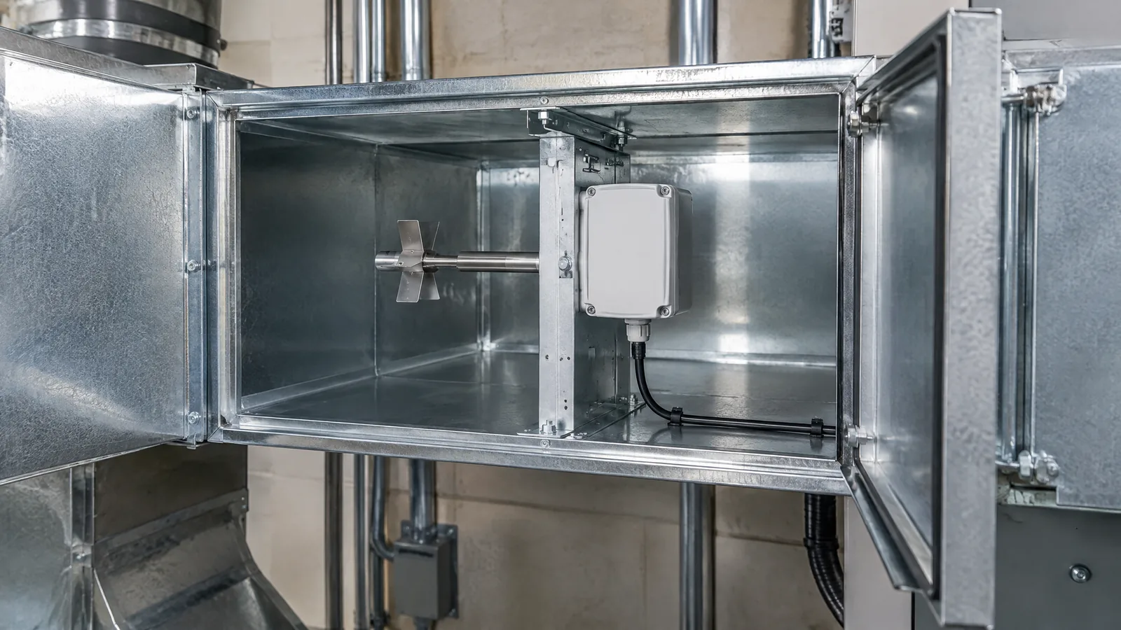
A fan setting can say what a controller requested, but it cannot confirm how much air is actually moving through a supply, return or exhaust duct. An HVAC duct airflow sensor, usually part of a larger airflow station, measures a signal related to duct air movement so a building-control system can estimate flow under defined installation and calibration conditions.
This article is part of the computer hardware technology guide library.
Key takeaways
An HVAC duct airflow sensor is not always one standalone air sensor. An airflow station can combine a flow element, pressure sensing, signal conditioning and a building-automation input.
Differential pressure across a suitable duct flow element is one common route to an airflow estimate, but the result depends on the flow profile, duct geometry, air conditions and calibration.
Filter pressure drop and duct airflow are related building-service measurements, not interchangeable readings. A dirty-filter signal indicates loading across the filter; it does not by itself prove the room or duct airflow rate.
Use the station as an input to monitoring or control only after the installation, output range and commissioning method match the system.
- Treat the station as a measurement system, not a universal plug-in sensor.
- Keep optional components such as pressure transducers, pitot arrays, temperature compensation and BAS communications separate from the core concept.
- For formal verification or safety-critical work, follow the applicable project requirements and qualified engineering practice.
What does an HVAC duct airflow sensor measure?
The useful answer is usually an estimated air volume flow rate or air velocity at a defined duct location. The station does not measure a fan command. It measures a physical effect produced by moving air, then converts that effect into a value that a controller, display or building-automation system can use.
In a common differential-pressure arrangement, a flow element creates a pressure difference as air passes through or around it. A differential-pressure transducer measures that difference. Electronics then apply the station's documented relationship and configuration to estimate airflow. The relationship is not automatically linear, and the result is not meaningful if the element, duct size or configuration is wrong.
A station may be used on supply air, return air, exhaust air or outside-air paths. The selected location changes the question being answered. A supply measurement can help show what an air-handling unit is delivering, while an outside-air measurement can help monitor a ventilation input. Those are application choices, not properties every model provides.
What parts can a duct airflow measuring station include?
The word station matters because the installed assembly can contain several parts. The physical flow element may be a pitot-style array, averaging tube, grid or another manufacturer-defined design. Small pressure pickup points route signals to a differential-pressure instrument. The instrument may output a voltage, current, digital value or another signal to the controller.
Some projects add temperature or static-pressure inputs for compensation or diagnostics. A local display, data logger, network interface or building-automation protocol may also be present. These are optional or model-specific components, so a description of one installation should not be presented as the definition of every HVAC airflow measurement sensor.
The sensing element and the instrument are also distinct. The element interacts with the moving air. The pressure transducer converts a pressure difference into an electrical signal. A controller applies configuration and logic. A BAS may trend the value, show an alarm or use it in a control sequence. A technician still needs the documentation for the exact signal, scaling, power and environmental limits.
NIST's flow-meter overview lists pitot tubes as air-speed sensors and discusses how real flow profiles and nearby elbows can affect measurement work. That is a useful reminder that the instrument name alone cannot describe the finished measurement quality.
How differential pressure helps estimate duct airflow
Differential pressure is a difference between two pressure points. A duct station uses that difference as evidence of air movement through a known flow arrangement. The controller or transmitter then uses the station's calibrated relationship to estimate flow. It should not simply treat any pressure difference in any duct as an accurate airflow reading.
The duct profile matters. Bends, dampers, transitions, fans and obstructions can make the velocity distribution uneven. A station installed too close to a disturbance may see a profile that does not match the conditions used for its setup. NIST specifically notes profile effects in real pipe configurations and calibration effects for air-speed instruments; the same installation principle is relevant when planning duct measurement points.
The reading can also change when the system operates outside its intended range. Pulsation, turbulence, temperature and pressure changes can alter the relationship between the measured signal and the reported flow. That does not make the station useless. It means the result must be interpreted within the stated operating and commissioning conditions.
| Part or signal | What it contributes | What it does not prove |
|---|---|---|
| Duct flow element | Creates a defined pressure or velocity effect from moving air | That the element is suitable at every duct size or location |
| Differential-pressure transducer | Converts a pressure difference into an electrical output | The final airflow value without correct scaling and installation |
| Controller or BAS input | Displays, trends or uses the configured estimate | That the command equals measured airflow |
| Filter pressure measurement | Shows pressure drop across a filter and can indicate loading | The airflow delivered to a room or branch duct |
Airflow station versus HVAC filter pressure sensor
These measurements are often discussed together because both can use differential pressure, but they answer different questions. A filter-status arrangement compares pressure on the inlet and discharge sides of the filter. As particles collect, the pressure difference can rise. Setra's HVAC guidance says the high port should measure the filter inlet and the low port the discharge side, and that threshold choices should follow the filter manufacturer and system designer.
A duct airflow station instead uses a flow element and its defined measurement relationship to estimate air movement at a selected duct section. A filter can be clean while airflow is low because a fan, damper or other part of the system is not delivering the requested condition. Conversely, a filter can show increased pressure drop while the system is still moving air. Do not substitute one signal for the other in a control sequence.
This distinction also prevents a common beginner error: calling every differential-pressure tube a duct airflow sensor. Identify what the two pressure ports connect to, what physical element is in the duct and what the instrument has been configured to calculate before interpreting the number.
Where a building can use the measurement
A station can provide an input for monitoring or control on an air-handling unit, ventilation branch, exhaust duct or return-air path. The control objective might be to observe whether a commanded operating state produces the expected flow, to trend changes over time or to support a documented sequence that uses measured airflow. The station does not decide the complete HVAC strategy by itself.
For outside-air measurement, the important question is whether the installed instrument and location are appropriate for the required ventilation sequence. For exhaust, the system designer may care about a stable measured flow or an alarm when flow falls outside a configured range. For supply air, the reading can help compare a control request with a delivered condition. Each use needs its own setpoints and acceptance method.
Avoid turning an airflow value into an unsupported indoor-air-quality or health claim. Airflow is one input among many, and a generic article cannot establish that a particular station makes a building safe, comfortable or compliant. A project should use the relevant design documents, manufacturer instructions and applicable standards.
Installation and commissioning limits
The station's reading is only as useful as the installed measurement path. Confirm the duct dimensions, flow direction, element orientation, pressure tubing, transmitter range, signal scaling and controller configuration. Check whether nearby bends, dampers, transitions or fans are consistent with the manufacturer's installation requirements. These checks are engineering and commissioning tasks, not a reason to improvise a live building modification from a general article.
NIST explains that accurate flow measurement depends on the fluid, temperature, pressure, flow and installation conditions. For HVAC air, those variables can change with operating state and season. A value that looks precise on a screen can still be unsuitable if the installation was never commissioned against an appropriate reference or if the station is being used outside its specified range.
ASME PTC 19.5 describes techniques and methods for flow measurements used by Performance Test Codes, including alternative methods for special situations. It is a standards resource, not a universal replacement for a project's requirements. Formal testing, balancing, compliance work and safety-related decisions should be handled through the responsible HVAC or instrumentation professionals.
For a beginner reading a BAS trend, record what the point is labelled to measure, its units, the duct location and whether the point is raw pressure or calculated airflow. Do not compare two points until their units, scaling and measurement purpose are clear.
HVAC duct airflow sensor FAQs
These answers describe the general measurement concept. The model documentation and the building's design and commissioning records take priority for a real installation.
Is an HVAC duct airflow sensor a single physical sensor?
Not always. The phrase can refer to a complete airflow station made from a duct flow element, pressure pickups, a differential-pressure transducer and signal processing. Temperature inputs, displays and BAS communications may be optional or model-specific.
Does a duct airflow station measure fan speed?
No. Fan speed or a fan command can be another point in the system. An airflow station measures a physical signal associated with air movement and estimates flow under its configured conditions. A fan setting is not proof of delivered airflow.
Is filter differential pressure the same as airflow?
No. Filter differential pressure indicates the pressure drop across the filter and can indicate loading. Airflow measurement uses a suitable flow element and relationship for the duct. Both signals may be useful, but they should not be substituted for one another.
Can any pressure sensor be used as a duct airflow sensor?
No. The pressure instrument, flow element, tubing, range, installation and configuration must suit the intended measurement. A pressure difference without a defined relationship to duct flow cannot automatically provide a reliable airflow value.
Why can two airflow readings disagree?
They may be measuring different locations or purposes, or they may have different scaling, installation conditions, flow profiles, ranges or commissioning references. Check the point definition and the installation before treating the disagreement as a failed sensor.
About the image
AI-generated editorial illustration; not an actual product or mission photograph.
Source notes
Reporting record
techduopulse stores source destinations privately. Public notes remain non-clickable so every visitor journey stays on this website.
Source note: Setra HVAC filter status and airflow application guidance
Primary source · Differential-pressure filter monitoring, airflow stations, port orientation and threshold cautionsSource note: NIST flow-meter and air-speed measurement overview
Primary source · Installation and calibration conditions, pitot tubes, velocity-profile effects and flow-meter methodsSource note: ASME PTC 19.5 flow-measurement standard description
Primary source · Flow-measurement techniques, alternative methods and relationship to Performance Test CodesInitial 15 October 2026 India-focused application explainer. Separates an HVAC duct airflow station from a generic flow sensor and from filter differential pressure; distinguishes optional flow elements, transducers, compensation and BAS components; and qualifies installation, profile, calibration and standards limits without unsupported performance or safety claims.


