A launch vehicle can behave differently in flight than a ground model suggests, yet adding a separate wired instrument for every point makes the measurement system heavier and harder to manage. Fiber-optic strain and temperature sensor (FBG/OFDR) technology gives researchers another approach: changes in reflected light wavelength can reveal strain and temperature at many points along a fibre, while the laser interrogator and data system turn those optical changes into engineering data.
This article is part of the emerging technology science guide library.
Key takeaways
Fiber-optic strain and temperature sensor (FBG/OFDR) systems are distributed measurement systems, not just a piece of fibre. NASA research describes them as a way to collect dense structural data while keeping the sensing fibre small and light.
The fibre is the transducer path; a tunable laser, optical interrogator, signal processing and data-acquisition equipment are still needed. The full system may also connect to telemetry or recording equipment.
NASA’s work is research and development evidence. It does not mean every rocket uses FBG/OFDR, or that the technology replaces every accelerometer, thermocouple, strain gauge or operational sensor.
What does a fiber-optic sensor measure on a launch vehicle?
A fiber-optic strain and temperature sensor (FBG/OFDR) measures changes that affect the light travelling through or reflected from a prepared section of optical fibre. In NASA’s FOSS description, strain and temperature appear as changes in reflected wavelength from a laser source. Strain indicates how a monitored part deforms; temperature is a separate physical quantity that can affect the reading and can also be measured directly by a suitable sensing element.
This makes the technology useful for research into structural response and thermal conditions during a flight test. It can place many measurement points along a small fibre rather than treating every point as a separate copper-wired instrument. The value is not that one fibre magically observes everything. The value is that an optical measurement chain can gather a dense set of readings when the fibre, sensing regions, interrogator and data system are designed and qualified for the job.
How FBG and OFDR turn light into engineering data
A fiber Bragg grating, or FBG, is a deliberately written region in the fibre that reflects a narrow range of wavelengths. When the local strain or temperature changes, the reflected wavelength shifts. An interrogator sends light into the fibre, analyses the returned spectrum and converts the shift into a calibrated measurement.
Optical frequency domain reflectometry, or OFDR, uses a swept or tunable laser and signal processing to resolve responses along the fibre. NASA’s FOSS presentation describes a workflow that moves from the wavelength domain through processing and calibration to strain conversion. The practical output is therefore not raw light alone, but a time- and position-related data stream interpreted by software and electronics.
FBG and OFDR are related approaches, not interchangeable labels for one universal sensor package. A project may use one or both according to its measurement range, spatial resolution, sample-rate needs and environmental qualification. Those choices are engineering decisions outside the scope of this overview.
Why launch-vehicle researchers are interested
NASA’s FOSS material highlights three potential advantages for flight research: high spatial density, low sensor weight and resistance to electromagnetic or radio-frequency interference. It also describes fibres as potentially embeddable in structures and says one optical fibre can multiplex hundreds of sensors. These are system-level advantages reported in NASA research, not a guarantee for every installation or mission.
The same presentation connects FOSS with the need to validate structural models. NASA’s launch-vehicle instrumentation paper explains that development flight instrumentation exists because analytical models retain uncertainty and vehicle-level testing can reveal responses that ground tests or earlier assumptions did not capture. Dense fibre measurements could help researchers compare the observed strain and temperature field with those models.
NASA also describes research into shape, loads, liquid level and cryogenic propellant-related measurements. Those examples should be read as separate or developing capabilities. A strain-and-temperature article should not imply that a basic fibre installation is automatically a propellant gauge, a navigation sensor or a flight-control input.
The sensor is only one part of the measurement chain
The physical fibre and its grating or sensing regions are the optical sensing element. They are not the whole launch-vehicle instrument. A complete FBG/OFDR arrangement can include a tunable laser or interrogator, optical connections, signal conditioning, calibration and processing, a data-acquisition unit, power, and—when required—telemetry or onboard recording.
NASA’s DFI paper lists data-acquisition units, sensors, telemetry, harnessing, mounting provisions, multiplexers and recorders as typical components, while stressing that not every system needs all of them. This distinction matters when a diagram or product description calls the fibre itself “the sensor system”. The fibre may be light and small, but the supporting electronics and environmental provisions still have to meet the flight-test requirements.
The research context also matters. NASA’s presentation discusses development toward higher sample rates and specialised cryogenic work. A project cannot infer a universal bandwidth, temperature range, accuracy or readiness level from those programme-specific examples.
Limitations and what the evidence does not prove
FBG/OFDR does not remove the need for calibration, environmental testing or a carefully specified data path. NASA’s launch-vehicle instrumentation paper warns that harsh environments can push commercial hardware beyond its usual conditions and that environmental requirements need to be established early. Optical immunity to electromagnetic interference does not by itself prove immunity to every mechanical, thermal, connector or installation failure.
Sampling speed is another boundary. NASA’s FOSS deck describes an earlier system limited to one sample every 90 seconds and later development aimed at higher rates, including a programme goal related to acceleration. These figures show that interrogator architecture and mission requirements matter; they are not a specification for every FBG or OFDR system.
Finally, research demonstrations are not the same as routine operational deployment. The supplied NASA sources support a credible development story for flight research and launch-vehicle instrumentation. They do not support claims that all current rockets carry these sensors, that they replace operational avionics, or that they make a vehicle safer by themselves.
Frequently asked questions
These answers use NASA’s FOSS and development-flight-instrumentation documents as technical context and keep research capability separate from universal flight practice.
Is an FBG sensor the same as an OFDR sensor?
No. FBG describes a grating-based sensing element, while OFDR describes an optical-frequency-domain interrogation and measurement approach. NASA presents them together in FOSS, but a project’s exact fibre, interrogator and processing design is application-specific.
Can fiber-optic sensors measure both strain and temperature?
Yes, NASA’s FOSS description says its system measures strain and temperature through changes in reflected wavelength. The calibration and sensing arrangement must distinguish temperature effects from strain for the intended measurement.
Do fiber-optic sensors replace all rocket sensors?
No. NASA describes possible uses alongside a broader development-flight-instrumentation system. Launch-vehicle systems can still use conventional or other sensors for vibration, acceleration, force, pressure, heat flux and other measurements.
Are these sensors already standard on every launch vehicle?
The supplied evidence does not support that claim. It documents NASA research, flight-test experience and development activity, so the appropriate description is research and development rather than universal operational adoption.
Why is a separate interrogator needed?
The fibre changes or reflects light, but electronics must provide the optical source, analyse the returned wavelength information, apply calibration and deliver usable data to acquisition, telemetry or recording systems. The fibre is one component of that chain.
About the image
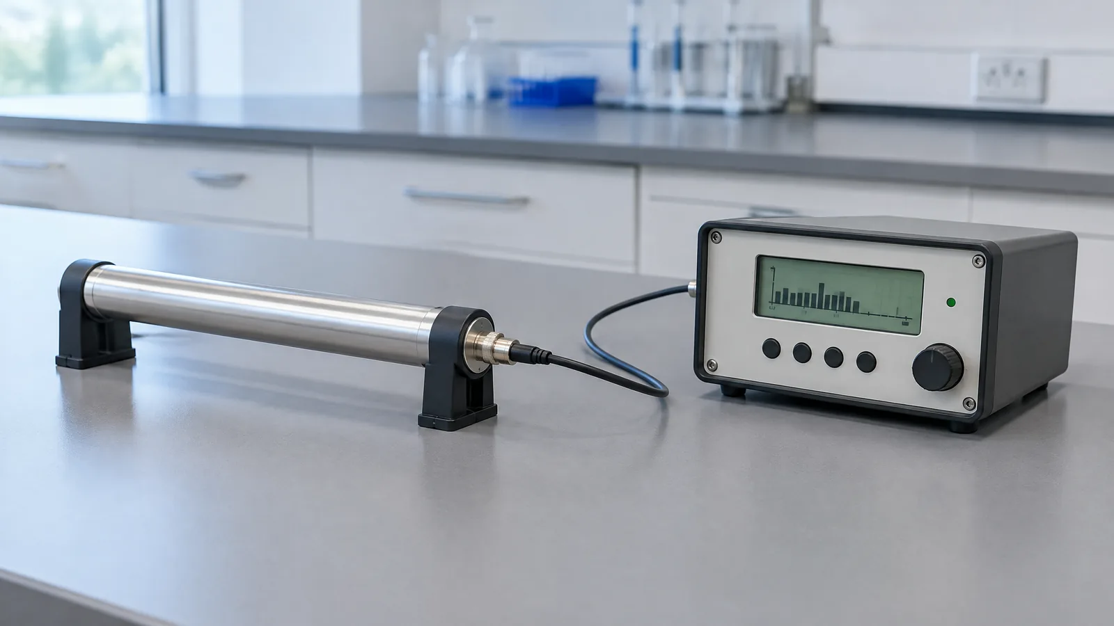
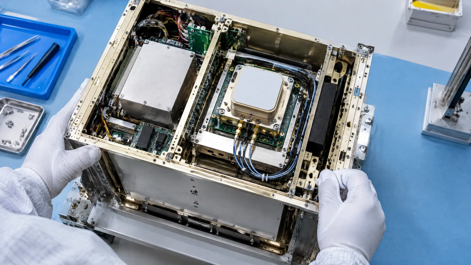
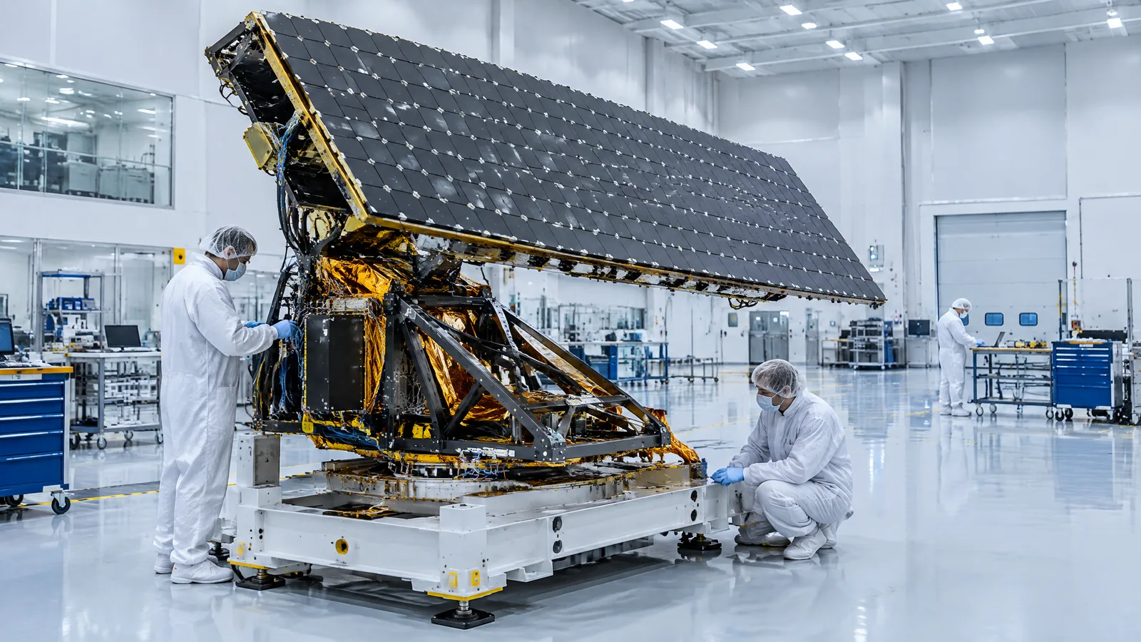
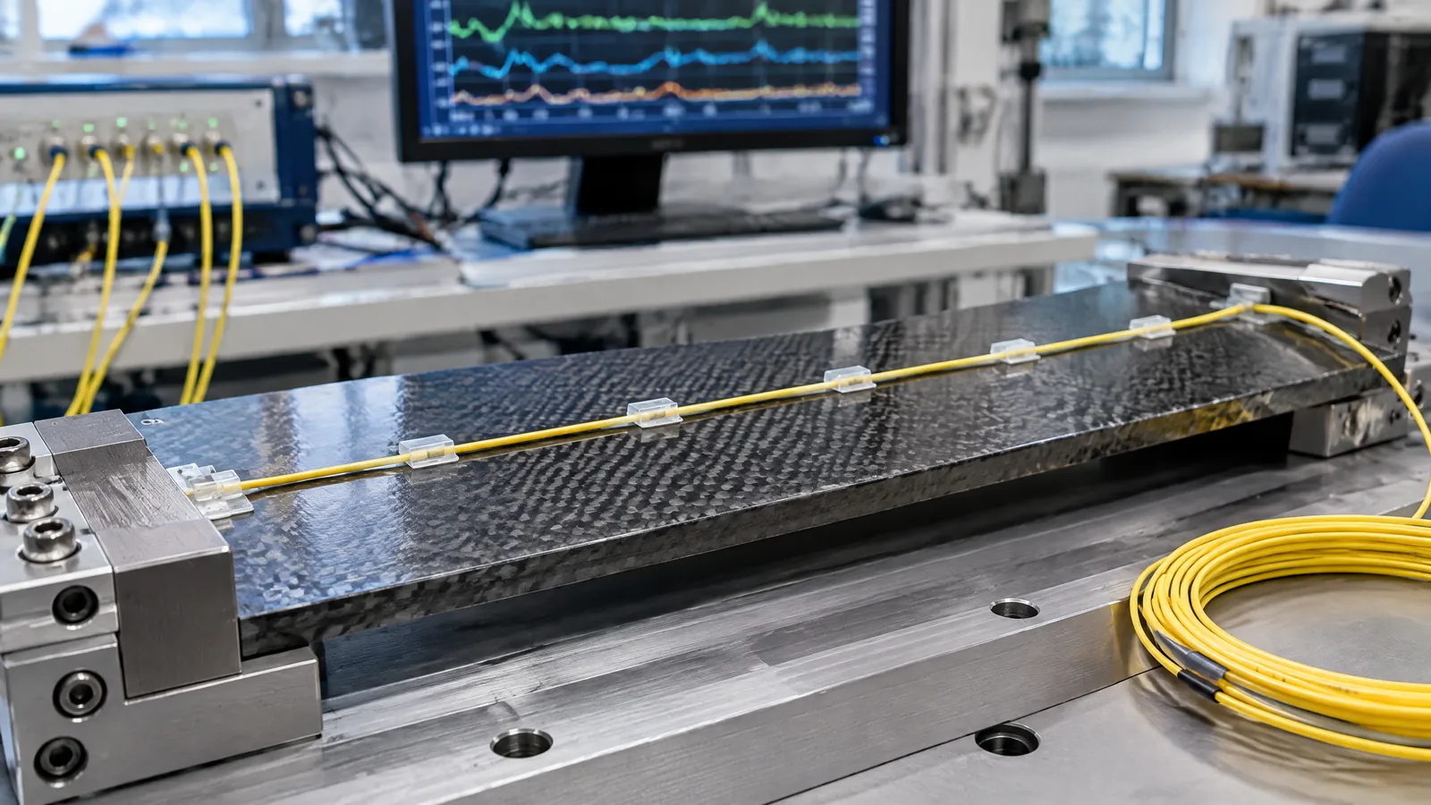
AI-generated editorial illustration; not an actual product or mission photograph.
Source notes
Reporting record
techduopulse stores source destinations privately. Public notes remain non-clickable so every visitor journey stays on this website.
Source note: NASA launch-vehicle development-flight-instrumentation design paper
Primary source · Vehicle-level instrumentation purpose, sensor distinctions, supporting hardware and harsh-environment requirementsSource note: NASA fiber-optic sensing technology briefing
Primary source · FOSS operating principle, FBG/OFDR, multiplexing, potential launch-vehicle and aircraft applications, development caveatsInitial 15 October 2026 India-facing explainer based on two supplied NASA primary technical sources. It explains FBG/OFDR measurement principles and launch-vehicle research context, separates the fibre from interrogator and data-system components, and qualifies research-stage and model-specific claims without presenting installation or propulsion guidance.