
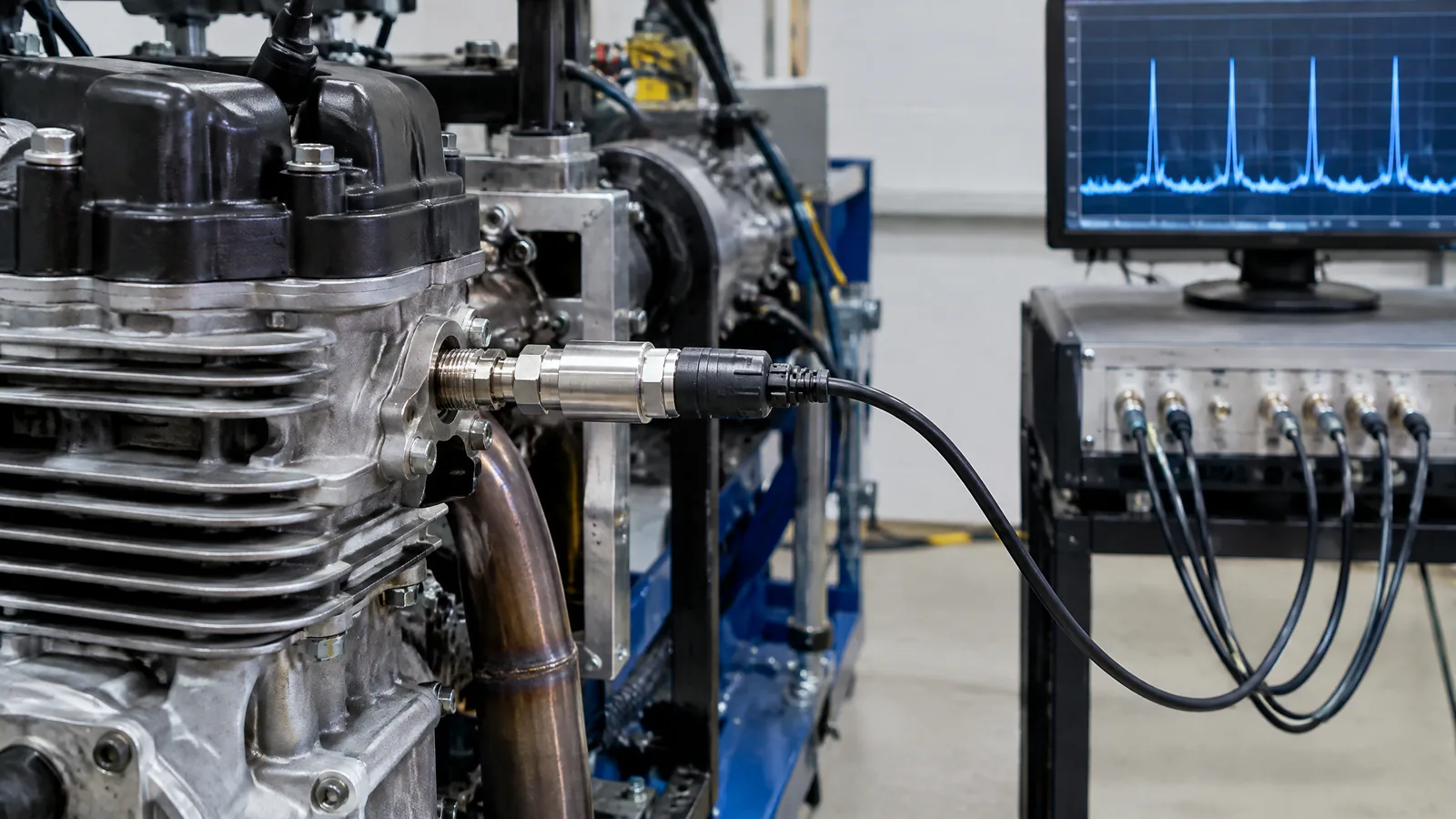
A rocket-engine test can look normal on a slow pressure display while rapid oscillations are hidden between readings. A dynamic combustion-pressure sensor measures fast pressure changes in or near the combustion-test environment so engineers can examine pressure fluctuations and possible combustion-instability signals; it is a specialised test instrument, not a general replacement for a static pressure sensor.
This article is part of the computer hardware technology guide library.
Key takeaways
Dynamic combustion-pressure sensors are used to observe changing pressure behaviour during rocket-engine ground tests. They complement, rather than automatically replace, instruments intended to follow steady pressure.
Piezoelectric pressure sensing is suited to fast-changing events because the sensing element produces an electrical charge when it is stressed. The complete measurement still depends on signal conditioning, cabling, acquisition and calibration information.
A high-speed pressure channel is only one part of a test system. NASA Stennis lists dynamic pressures alongside accelerometers, strain gauges and microphones in its high-speed data-acquisition system, while pressure transducers and transmitters serve other measurement roles. [2]
Temperature, vibration, shock, sensor exposure, mounting and the test stand’s acquisition chain can all affect interpretation. Source-specific limits must not be treated as universal specifications.
- Use the dynamic/static distinction to match the instrument to the question.
- Keep the physical pressure sensor separate from external amplifiers, cabling and data-acquisition hardware.
- Treat combustion-instability interpretation as a qualified test-engineering task, not a DIY diagnostic.
What does a dynamic combustion-pressure sensor measure?
A dynamic combustion-pressure sensor records how pressure changes with time during an engine test. The useful signal may include rapid peaks, oscillations or other changing behaviour that a slow trend channel can smooth out or miss. In this context, “dynamic” describes the time behaviour of the measurement, while “combustion pressure” identifies the engine-test environment being observed.
The sensor does not directly announce that an engine is stable or unstable. It produces a signal that a test team can compare with other channels and with the approved test model. Kistler describes dynamic pressure and vibration monitoring as part of understanding fuel injection and mixing, ignition and combustion in rocket-engine testing. [1]
This is narrower than the broad idea of a pressure sensor. A general pressure guide explains the underlying chain as pressure changing a diaphragm or sensing element, followed by an electrical change and signal conditioning. The rocket-test application adds a demanding time scale, environment and data-quality question.
Why piezoelectric sensing is associated with fast pressure changes
In a piezoelectric design, mechanical stress on the sensing element produces electric charge. The charge is then handled by suitable signal-conditioning electronics before the acquisition system records it. This makes the approach useful for changing events, but the pressure-sensitive element is not the same thing as the amplifier, cable or digitiser.
Kistler distinguishes dynamic pressure measurement from long-term static pressure monitoring. Its rocket-testing material describes piezoelectric pressure sensors for dynamic, high-temperature and cryogenic applications, while it identifies piezoresistive sensors for static monitoring and propellant-flow control in the stated test context. [1] That is an application distinction, not a rule that one technology is always better.
A static channel answers a question such as “how is the pressure trend changing over a longer interval?” A dynamic channel asks “what rapid pressure behaviour occurred during this event?” A test stand may need both channels because they describe different parts of the same engine run.
How the sensor fits into a rocket hot-fire measurement chain
The physical sensor is only the first link in the chain. A simplified view is: pressure event → sensing element → electrical charge or signal → conditioning → digitiser → time-aligned record → engineering interpretation. Every link needs to match the measurement task. A sensor with a fast response cannot compensate for an unsuitable acquisition channel or poor time synchronisation.
NASA Stennis describes a high-speed data-acquisition system operating at 102,400 samples per second in its presentation and lists dynamic pressures among its high-speed measurements. It separately describes pressure transducers, signal conditioning and engineering-unit scaling using calibration-report information. [2] These examples show why “the sensor” and “the instrument system” should not be treated as interchangeable terms.
Other physical sensors may be recorded beside the pressure channel. NASA lists accelerometers, and its presentation explains that vibration data can support structural-model validation and turbopump-health monitoring. Kistler also discusses pressure and vibration monitoring together. An accelerometer measures motion or vibration; it is not a second name for the combustion-pressure sensor. [1] [2]
| Component or channel | What it contributes | Why it must stay distinct |
|---|---|---|
| Dynamic pressure sensor | Time-varying pressure signal in the selected engine-test location | The primary pressure-sensitive element; its response depends on its design and environment |
| Static pressure instrument | Longer-term pressure monitoring or process control | A steady-pressure task is not the same as capturing fast fluctuations |
| Accelerometer | Vibration or structural motion data | It can support a combined analysis but does not measure combustion pressure |
| Conditioner, cable and data acquisition | Excitation or charge handling, digitisation, timing and recording | These are external instruments and signal-path elements, not the physical sensor |
What can limit or distort the reading?
The pressure trace is meaningful only when the sensor and the full test channel are suitable for the environment. Fast pressure events can occur alongside heat, vibration, shock and demanding diaphragm exposure. Kistler describes high-pressure sensing during ignition as a case involving high peaks and fast-rising thermal-shock events, and gives application-specific high-temperature examples. Those figures belong to the cited equipment context; they are not a safe operating target for an unspecified sensor. [1]
Temperature can change sensor behaviour and electronics. Vibration can appear in more than one channel. The physical connection can alter what reaches the sensing element, while the acquisition rate and filtering can change how a recorded event appears. A test team therefore has to understand the sensor’s response, calibration record, timing and channel configuration before interpreting a waveform.
This article does not provide chamber-design, installation, wiring, calibration or mitigation instructions. Rocket hot-fire systems involve high-energy fluids, hot gases and specialised test-stand controls. Selection and use belong to authorised propulsion and instrumentation professionals following the applicable facility procedures.
Frequently asked questions
The answers below keep the sensor’s educational scope separate from a real test procedure.
What is a dynamic combustion-pressure sensor?
It is a pressure-sensing instrument used in rocket-engine ground testing to observe pressure changes over time, including rapid fluctuations and peaks. It is a specialised measurement channel, not a universal replacement for a static pressure instrument.
Why is a piezoelectric pressure sensor used for rocket testing?
Piezoelectric sensing produces charge when the element is mechanically stressed, making it useful for changing pressure events when paired with suitable signal conditioning and data acquisition. The correct choice still depends on the test environment, response needs and calibration information.
Is a dynamic pressure sensor the same as an accelerometer?
No. A pressure sensor measures pressure, while an accelerometer measures vibration or motion. Both may be recorded during an engine test because their signals can describe different aspects of the event.
Can a static pressure sensor capture combustion instability?
Not necessarily. A static-pressure channel may be appropriate for longer-term pressure monitoring, but fast combustion-related behaviour requires an instrument and acquisition path suited to the relevant dynamics. The application and sensor specification must be checked by the test team.
Can I build or install one for a home rocket project?
This article is not a build or installation guide. Rocket hot-fire measurement involves hazardous pressure, heat and propellant systems, so sensor selection, mounting and testing should be left to qualified teams operating an authorised facility with documented procedures.
About the image
AI-generated editorial illustration; not an actual product or mission photograph.
Source notes
Reporting record
techduopulse stores source destinations privately. Public notes remain non-clickable so every visitor journey stays on this website.
Source note: NASA Stennis Space Center rocket-engine hot-fire sensor presentation
Primary source · Capabilities; pressure transducers; high-speed sensors; accelerometers and data-acquisition systemsSource note: Kistler rocket-engine testing measurement guidance
Primary source · Dynamic pressure and vibration monitoring; static pressure monitoring; high-temperature and ignition-pressure application notesNew India-facing application explainer for the dynamic combustion-pressure sensor. It separates dynamic and static pressure tasks, distinguishes the physical pressure sensor from accelerometers and external signal-chain instruments, attributes source-specific sampling and environmental examples, and excludes unsafe propulsion, installation and calibration instructions.


