
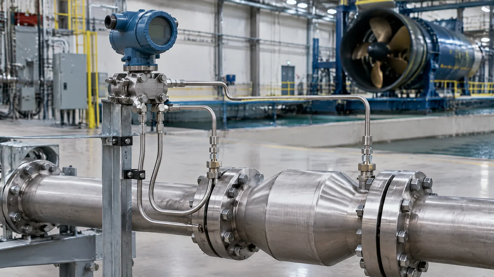
When a rocket test team wants to know whether pressure is changing across a line, valve or other component, one pressure number is not enough: the two sides must be compared. A differential-pressure transducer measures that difference between two ports, while the test system records and interprets the result; it does not directly measure flow or tell engineers how to redesign an engine.
This article is part of the computer hardware technology guide library.
Key takeaways
A differential-pressure transducer reports the pressure at one port relative to the pressure at another port. In rocket testing, that delta can help compare conditions across a fluid path or component during a controlled test.
The transducer is only one part of the chain. Sense lines or connections, signal conditioning, calibration information and a data-acquisition channel affect what the final number means.
Port orientation, medium, temperature, response speed, pressure range and calibration status matter. A plausible-looking delta is not automatically a valid measurement.
What does a rocket differential pressure sensor measure?
A differential-pressure transducer measures the difference between two pressures. One connection is commonly labelled high or P1 and the other low or P2, but the exact naming and sign convention belong to the instrument documentation. The output represents the relationship between those two points, not pressure against a vacuum and not pressure against the surrounding atmosphere.
For a rocket-engine test, the two pressure points may be selected on opposite sides of a component or along a fluid route. The resulting delta can show that the two locations are experiencing different conditions. NASA Stennis lists pressure and delta-pressure channels among the typical measurements used in rocket-engine hot-fire test data systems. That is evidence that delta pressure is a distinct test channel, not merely a casual name for any pressure reading.
A useful mental model is: pressure at point A minus pressure at point B equals the reported difference. The subtraction direction matters. Reversing the ports can reverse the sign even when the physical system has not changed. Always read the port labels, units and reference direction together.
How the measurement chain works
Inside a transducer, pressure applied through the two ports produces a small mechanical change in a sensing element. Depending on the model, that change can be converted into an electrical output by a strain-based, piezoresistive, capacitive or other sensing construction. The electronics and test system then turn the signal into a pressure-difference value. The exact construction is model-specific, so the label differential-pressure transducer is not a complete datasheet.
The physical transducer may connect to the points of interest through sense lines or other approved interfaces. NASA’s Stennis presentation describes pressure transducers mounted near the point of interest using a sense line, with signal conditioning supplying excitation and reading the sensor output. This makes an important distinction: a line, connector or amplifier is not itself the pressure sensor, although each can affect the measurement.
A simplified chain is: two pressure points → transducer → excitation and signal conditioning → digitizer or transmitter → calibrated engineering-unit value. Some systems use a direct low-level bridge output; others use a transmitter with a standardised current output. The acquisition hardware and scaling rules must match the device and its calibration information.
- Physical sensor: the transducer compares pressure at its two ports.
- External or model-specific parts: sense lines, fittings, isolation hardware, excitation, signal conditioning and transmitters.
- Instrument and software layer: digitizer, time base, channel configuration, calibration coefficients and analysis display.
Why rocket testing needs more than a pressure number
Rocket test environments can combine changing pressure, vibration, heat, cryogenic media and fast transients. Kistler’s rocket-engine testing guidance separates long-term static pressure measurement from dynamic pressure and vibration monitoring. It describes piezoresistive technology for static measurements and piezoelectric pressure sensors for dynamic work, while also discussing cryogenic applications and high-pressure ignition events.
That distinction prevents a common mistake: choosing a sensor because it measures pressure without checking whether it can respond to the event being studied. A slowly changing comparison and a sharp ignition transient are different measurement tasks. Temperature, vibration, line volume, mounting and the measured medium can influence the response. The suitable instrument is therefore determined by the test requirement and approved facility practice, not by the word rocket alone.
The transducer also does not measure every variable in the test. A separate flow sensor, thrust measurement, temperature sensor, accelerometer or position channel may be needed for other questions. Kistler and NASA both describe these as separate measurement categories. A delta-pressure channel should not be presented as a substitute for them.
How to read a differential-pressure test channel
Before interpreting a graph or logged value, identify what the channel actually represents. Start with the two port locations and the sign convention. Then check the pressure units, expected range, medium, temperature conditions and whether the channel is intended for static, changing or dynamic behaviour. Without these details, a positive or negative number has little standalone meaning.
- Confirm which physical points are connected to the two ports and which direction is defined as positive.
- Check the transducer range, output type, excitation or supply requirements and the calibration record for that specific device.
- Find out how sense-line layout, mounting, temperature and vibration could influence the reading.
- Check how the data system converts the raw signal into engineering units and whether timestamps align with other test channels.
- Treat an unexpected result as a measurement question first; do not infer an engine fault or change a propulsion design from one unverified channel.
Limitations and safe scope
A differential-pressure reading can be wrong, incomplete or misinterpreted even when the display is working. Port misidentification, blocked or unsuitable lines, temperature effects, electrical scaling errors, calibration drift and transients outside the instrument’s intended response can all change the result. A transducer also reports a difference; it cannot by itself identify which side caused the change.
Rocket propulsion tests involve high-energy fluids, pressure and potentially hazardous environments. This explainer is not a build, firing, control or diagnostic procedure. Do not connect, disconnect, calibrate or pressure-test hardware on a live or pressurised system from general online advice. Those decisions belong to the authorised test organisation, the instrument documentation and its qualified safety and measurement procedures.
Frequently asked questions
Is a differential-pressure transducer the same as two separate pressure sensors?
Not necessarily. A differential-pressure transducer is designed to compare two pressure inputs in one instrument, while two separate sensors can measure two channels that are compared later. The architecture, calibration and timing are different, so the system documentation decides which arrangement is being used.
Does a rocket differential pressure sensor measure flow rate?
No. It measures a pressure difference. A test team may study delta pressure alongside a dedicated flow measurement, but flow cannot be inferred safely from one differential reading without a validated system model and relevant conditions.
Why do the ports and sign convention matter?
The result is a difference between two inputs. Reversing the inputs can reverse the sign, and connecting the ports to different physical locations changes the question being measured. Port labels and the documented positive direction must be checked before reading a plot.
Which sensor technology is best for rocket testing?
There is no universal best choice. Static, dynamic, cryogenic and high-temperature measurements can require different sensor technologies and installation arrangements. The test requirement, medium, range, response and approved facility procedure should determine the selection.
About the image
AI-generated editorial illustration; not an actual product or mission photograph.
Source notes
Reporting record
techduopulse stores source destinations privately. Public notes remain non-clickable so every visitor journey stays on this website.
Source note: NASA Stennis Space Center rocket-engine hot-fire sensor presentation
Primary source · Pressure and delta-pressure channels; transducer, sense line, calibration and acquisition chainSource note: Kistler rocket-engine testing measurement guidance
Primary source · Pressure and vibration characterization; static versus dynamic pressure; cryogenic and ignition measurement limitsNew application article for rocket differential-pressure sensing. It explains the two-port difference concept, separates the physical transducer from sense lines, signal conditioning and acquisition hardware, distinguishes static and dynamic test contexts, and adds limitations and safety boundaries without prescribing propulsion design or live testing.


