A crankshaft position sensor is one of the quiet timekeepers inside an electronically managed combustion engine. It gives the engine control unit a repeating reference for crank angle and rotational speed, so fuel injection and ignition calculations can be synchronized to a moving mechanical system.
On this page 4 sections
Part of our computer hardware technology guide library
How a Crankshaft Position Sensor Creates the Engine Timing Reference
A crankshaft position sensor, often shortened to CKP, is a non-contact sensor that observes a target attached to or rotating with the crankshaft. The engine controller uses the resulting pattern to work out crankshaft position and speed; Bosch and DENSO describe that information as an input to injection and ignition timing calculations. [1] [2]
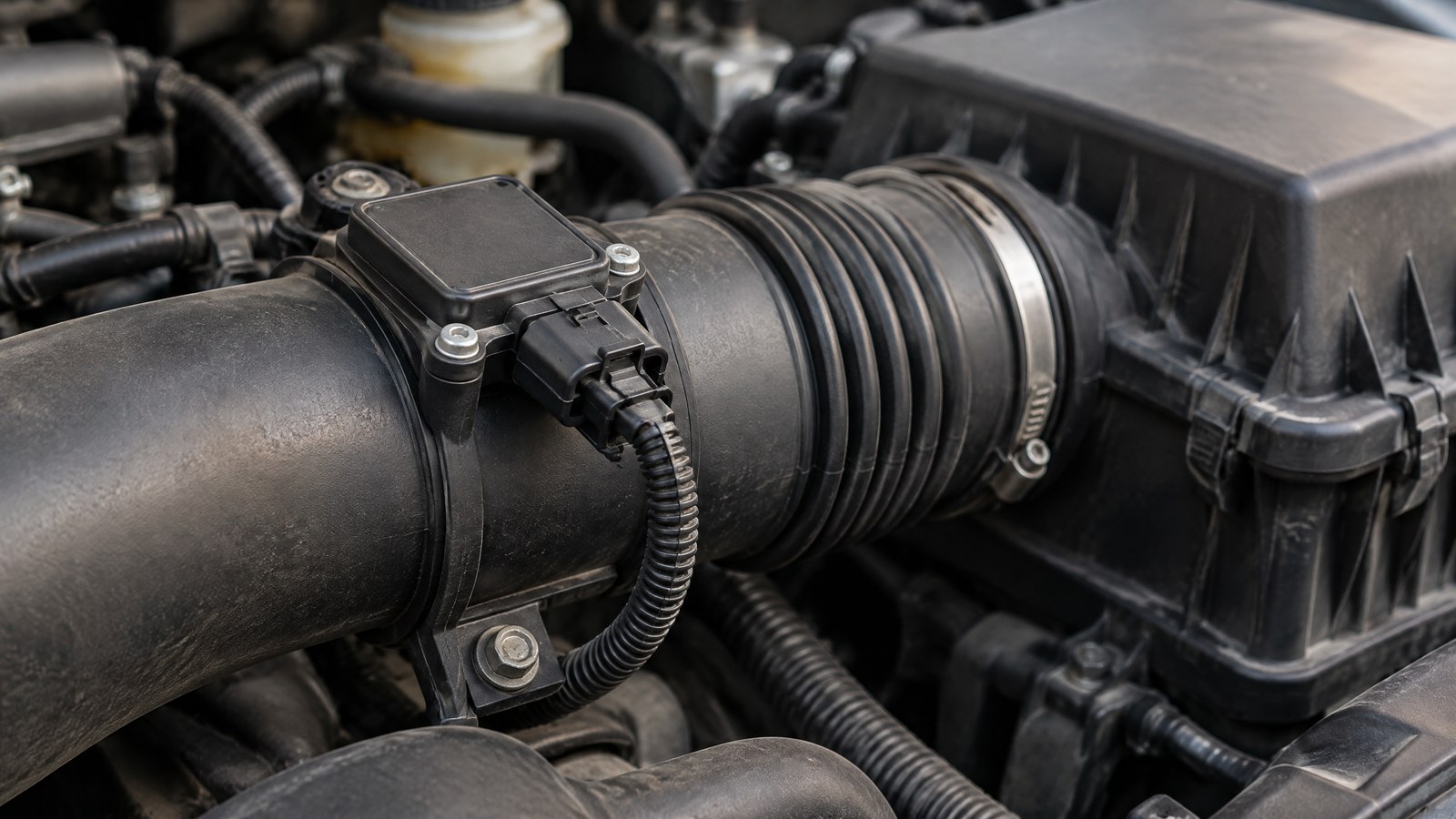
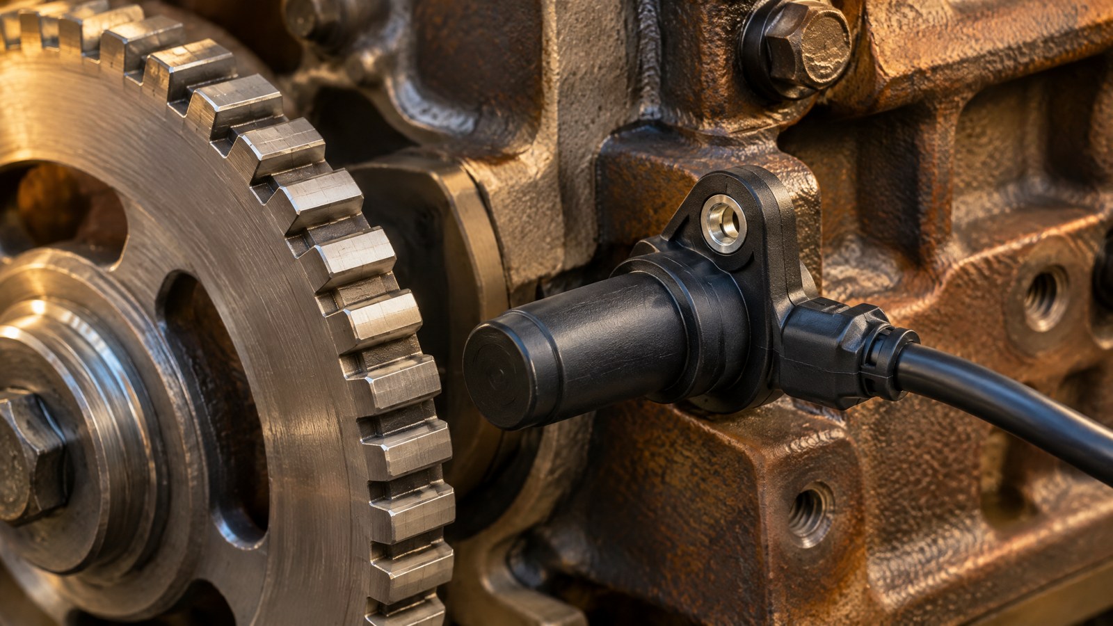
AI-generated editorial illustration of generic crankshaft timing hardware and engine context, not a photograph of a tested product or an actual field measurement.
The useful idea is not simply “a sensor knows where the engine is.” The controller needs a repeatable timing reference while the crankshaft is moving. That reference lets it relate software calculations to a particular part of the engine’s mechanical rotation. The exact target geometry, sensor placement and interpretation belong to the vehicle design, so there is no single universal CKP pattern or diagnostic rule.
From passing features to crank angle and rotational speed
A target wheel or equivalent rotating feature passes the stationary sensor as the crankshaft turns. DENSO describes a crankshaft sensor facing a timing rotor and counting the teeth that pass it. In simple terms, each detected feature is one event in an ordered sequence. The sequence gives the controller repeatable landmarks within a mechanical revolution, which is 360 degrees of crankshaft rotation. [2]
Speed comes from timing as well as position. If the interval between comparable events becomes shorter, the rotating target is moving faster; if it becomes longer, it is moving more slowly. DENSO notes that the rate of positional change is used to calculate rotational speed. This is why the sensor is often called a crankshaft speed sensor as well as a position sensor. [2]
That does not make every pulse an independently measured angle. The controller combines a vehicle-specific target pattern with time between events and its own timing model. The result is an engine-management reference, not a general-purpose measurement of engine condition.
Why a missing tooth can mark a reference
Many crank targets deliberately include a gap where a regular tooth or element would otherwise be. Bosch states that a missing element in the trigger wheel determines the reference point. The gap is therefore a designed timing signature, not automatically a sign of damage. [1]
At the concept level, the controller sees a repeating series of events and then an interval that is different from the regular pattern. Once it recognizes that pattern for the vehicle, it can treat the distinctive gap as a known reference within the revolution and calculate timing between successive events. EFIgnition describes this principle as using the defined missing tooth to establish a crank-angle reference. [5]
A “missing-tooth” description should never be treated as a repair specification. Tooth counts, reference alignment, signal processing and the relationship to engine timing differ by engine. A bent, contaminated or incorrect target can also change what a sensor sees, which is one reason component diagnosis needs the manufacturer’s procedure and qualified interpretation.
Crankshaft sensing and camshaft sensing answer different questions
The crankshaft position sensor answers where the crankshaft is within its repeating rotation and how quickly it is turning. A camshaft position sensor monitors the camshaft instead. DENSO says the camshaft signal helps the controller calculate camshaft angle and recognize which cylinder is firing, while Bosch describes its camshaft sensor as supplying exact camshaft position for injection, ignition and variable camshaft phasing. [2] [4]
These inputs are related but not interchangeable. In a four-stroke engine, crank position repeats while the engine cycle still needs phase context. Using the crank signal with camshaft information lets the controller relate the fast, repeating crank reference to valve-train phase and cylinder identity where the vehicle system requires it. The technical distinction matters more than a parts-list distinction: one signal tracks the crank’s rotation; the other adds information about camshaft phase.
For a broader explanation of the magnetic principle behind one common sensing approach, see [Hall-effect sensor basics](/article/hall-effect-sensor-explained).
Sensor technologies and the limits of the signal
Crankshaft sensors can use more than one sensing technology. Bosch lists Hall and inductive versions, while DENSO identifies inductive magnetic-pick-up and semiconductor magnetic-resistance types in its range. The shared purpose is to turn the movement of a suitable target into an electrical pattern the controller can interpret; their electronics and signal characteristics are not identical. [1] [2]
Littelfuse’s gear-tooth application note explains the Hall-effect version at a physical level: a passing ferrous tooth changes magnetic flux in the air gap, and the sensing electronics convert that change into a signal. It also shows why target material, geometry, alignment and operating conditions matter to a sensing system. Those factors are part of the engineered assembly rather than a reason to apply a generic adjustment rule. [3]
A CKP signal has clear limits. It does not, by itself, identify fuel quality, airflow, exhaust composition, mechanical compression or the reason for every warning light. It reports a motion reference. An implausible or absent reference can be important, but it must be assessed alongside vehicle-specific data and the condition of the target, wiring and related systems by a qualified professional.
Important Points / Key Information
Key Takeaways
- A crankshaft position sensor gives engine management a repeatable reference for crankshaft rotation and rotational speed.
- The controller derives useful timing context from the order and timing of detected target features, not from an isolated pulse alone.
- A deliberately missing target element can create a recognizable reference point when it is interpreted as part of the correct vehicle-specific pattern.
- Crankshaft and camshaft sensors can work together: the crank signal provides rotation reference, while the cam signal adds phase and cylinder context where needed.
- A warning lamp, misfire, stall or no-start concern is not proof that the sensor itself is defective; it warrants qualified, vehicle-specific assessment.
What a reported sensor concern can and cannot establish
A report that mentions crankshaft position should be read as a lead, not a verdict. DENSO lists several possible fault influences around camshaft and crankshaft sensing, including contamination, heat and wiring wear, while Delphi says an engine warning can arise from a range of issues beyond the crankshaft sensor. [2] [6]
That distinction is safety-relevant. Modern engine controls make decisions from connected mechanical, electrical and software inputs. Replacing a component or changing settings without a vehicle-specific diagnosis can miss the actual cause and create further risk. This explainer intentionally does not give testing, wiring, replacement, calibration or bypass instructions.
Examples / Supporting Information
The following examples explain the reference concept. They are not product tests, universal specifications or service instructions.
A published 60–2 target-wheel example
Bosch’s illustration for one commercial-vehicle crankshaft speed sensor labels a trigger wheel with a 60–2 pattern and explains that a missing element determines the reference point. In that notation, the pattern is based on 60 positions with two deliberately absent elements. It is a helpful example of how a distinctive gap can be designed into a target, but it is not a claim that all vehicles use that pattern. [1]
The value of the example is conceptual. Regularly spaced features support repeated speed and position events; the planned interruption makes one part of the repeating sequence distinguishable. The controller still needs the engine maker’s intended relationship between that reference and its control calculations.
Hypothetical signal interpretation
Hypothetical, not a test: imagine a rotating target that produces a regular succession of sensor events, followed by one noticeably longer interval at an engineered gap. A controller designed for that target can identify the unusual interval as a reference and use the surrounding event timing to track rotation. It can then pair that crank reference with other engine inputs as required.
If the expected pattern is not credible, a control system may record a concern or be unable to establish the reference it needs. That high-level description does not show which part has failed. A sensor, target, connector, wiring path, controller logic or another engine issue can call for different investigation under the correct vehicle documentation.
Hypothetical India-use context
Hypothetical: a commuter returns to a parked petrol hatchback after an ordinary office trip in Bengaluru and the engine does not start. A crankshaft reference is relevant at starting because the control unit needs position and speed information to coordinate engine events. But the symptom alone does not identify the sensor as the cause. [2] [6]
The practical response is not a roadside sensor fix. If a vehicle stalls or will not start in a location that creates a safety concern, prioritize occupants and traffic safety, then arrange appropriate assistance and qualified inspection using the vehicle maker’s information. This article makes no claim about a specific model, weather condition or real-world incident.
Conclusion
A crankshaft position sensor turns the ordered movement of a rotating target into the engine’s basic angle-and-speed reference. Its most interesting feature is the relationship between a physical pattern, often including a deliberate gap, and the controller’s ability to recognize a repeatable point in crankshaft rotation.
Understanding that reference also clarifies why a crankshaft sensor and a camshaft sensor are complementary, why target design matters, and why a symptom should not be mistaken for a component diagnosis.
How we checked thisSources (6)
We keep source links private so your reading stays on techduopulse. Each note names the publisher and document we checked.
Bosch Mobility: crankshaft speed sensor operating principle
Primary source · How a Crankshaft Position Sensor Creates the Engine Timing ReferenceDENSO: how camshaft and crankshaft sensors work
Primary source · From passing features to crank angle and rotational speedLittelfuse: Hall-effect gear-tooth sensing principle
Primary source · Sensor technologies and the limits of the signalBosch Mobility: camshaft position sensor operating principle
Primary source · Crankshaft sensing and camshaft sensing answer different questionsEFIgnition: missing-tooth trigger-wheel explanation
Primary source · Why a missing tooth can mark a referenceDelphi: cautious context for reported crankshaft-sensor concerns
Primary source · What a reported sensor concern can and cannot establishOwner-approved educational sensor explainer; obsolete private-draft status removed without changing source-backed facts or professional safety boundaries. Original generic AI editorial illustration, not a product or field-test photograph.