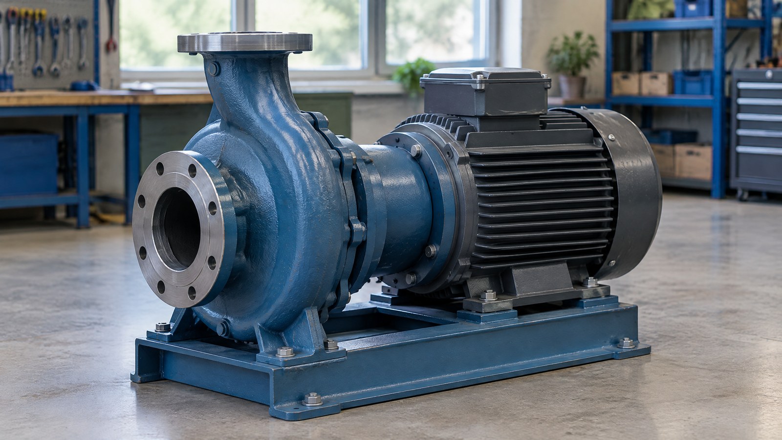
A centrifugal pump moves liquid by transferring energy from a rotating impeller to the liquid flowing through it. That energy helps water travel through pipes, reach an overhead tank or circulate through a cooling system—but the flow you get also depends on the installation around the pump.
On this page 10 sections
- How Does a Centrifugal Pump Work?
- Main Parts of a Centrifugal Pump
- Why Priming Matters
- Main Types and Where the Names Fit
- Flow Rate, Head and the System Around the Pump
- Applications: From Water Tanks to Industrial Circulation
- Common Problems and What They May Mean
- Important Points / Key Information
- Examples / Supporting Information
- Conclusion
Part of our computer hardware technology guide library
How Does a Centrifugal Pump Work?
In a common radial-flow centrifugal pump, liquid enters near the centre of the impeller, gains energy from its rotating blades and moves towards the outer edge. The surrounding casing collects the flow and guides it towards the discharge connection. KSB describes the impeller as the component that converts mechanical power into useful pump output [1] [2].
Think of water being moved from a ground-level storage tank to a rooftop tank. The pump does not create water or make it disappear from the lower tank. It adds the energy needed to move the available water through that particular pipe system.
Liquid reaches the impeller inlet
The centre opening of the impeller is often called its eye. Liquid reaches this inlet because of the pressure conditions in the supply system. In a flooded-suction arrangement, the liquid level is above the pump inlet; in a suction-lift arrangement, the pump sits above the source liquid level.
The familiar word “suction” can be misleading. It does not mean the pump can pull water through any height or clear an air-filled inlet line without help. Inlet conditions and pump design matter [4] [5].
The rotating impeller adds energy
A motor or another driver turns the shaft and impeller. As liquid passes between the impeller blades, the blades change its motion and transfer mechanical energy to it. In the radial-flow arrangement described here, liquid travels outwards towards the impeller rim [1] [2].
Not every rotodynamic pump has this exact flow path. Mixed-flow and axial-flow designs guide liquid differently. The radial-flow example is useful for understanding the familiar volute-shaped water pump, not as a drawing of every pump type.
The casing collects and directs the flow
The casing contains the pressurised liquid and directs it towards the outlet. A volute is a spiral-shaped collecting passage; some pumps also use stationary diffuser passages. KSB explains that a diffuser reduces flow velocity while increasing static pressure, with losses kept as small as practicable [3] [11].
A useful distinction: the impeller adds energy, while the stationary passages guide the liquid and recover some velocity energy as pressure. It would be inaccurate to say that all pressure is produced only in the casing.
Liquid leaves through the discharge
The discharge connection carries liquid into the delivery pipe. During normal operation with a suitable liquid supply, fresh liquid continues to enter as liquid leaves. The resulting flow depends on both the pump and the resistance of the connected system [6].
For related background, see our pressure sensor working principle guide. It explains how pressure is measured rather than how a pump supplies energy.
Main Parts of a Centrifugal Pump
The impeller and casing perform the main hydraulic work, but the shaft, bearings, seals and driver make that work possible. The exact construction changes with the application [2] [3].
Impeller and casing
The impeller is the rotating, bladed component that transfers energy to the liquid. Its shape influences the pump's characteristics and the kinds of liquid it can handle. A clean-water impeller should not be assumed suitable for sewage or liquid containing abrasive solids; those duties need a compatible design [2].
The casing surrounds the hydraulic parts, contains pressure and provides a route between the inlet and outlet. Its material and pressure rating must suit the liquid, temperature and intended duty [3].
Shaft, bearings and driver
The shaft transmits rotation from the driver to the impeller. Bearings support the rotating assembly. An electric motor is a familiar driver, although other arrangements exist.
Bearing lubrication is not the same in every pump. Some designs use product-lubricated bearings, while others use a separate lubrication arrangement. Do not assume that the pumped water cools and lubricates every bearing [3] [4].
Shaft seal and pipe connections
Where a shaft passes through the casing, a shaft seal helps control leakage and prevent unwanted air entry. The sealing arrangement may use a mechanical seal or another design suited to the pump [3].
Suction and discharge pipes connect the pump to the system. Foot valves, strainers and other fittings may be part of an installation, but they are not universal parts inside every centrifugal pump. Their selection affects inlet conditions, losses and maintenance access.
Why Priming Matters
Priming establishes the liquid-filled conditions a pump needs before it can deliver liquid reliably. KSB states that the suction line of a non-self-priming centrifugal pump must be primed before start-up [4].
Air and liquid behave differently inside the pump. A conventional pump designed to move water cannot normally evacuate an air-filled suction line leading down to a lower water level by itself [5]. That is why a motor can be running even though water is not being delivered.
Conventional and self-priming pumps are different
A self-priming pump has a design that can remove air from the suction line under its specified conditions. In one documented arrangement, liquid circulates through a separation chamber while air is discharged [5].
However, the self-priming device or casing can still require an initial liquid fill. “Self-priming” describes air-handling capability, not permission to operate without liquid. Follow the instructions for the particular model rather than treating the label as a universal start-up procedure [4] [5].
Dry running is not a harmless test
Operating without the required liquid can damage a pump. Grundfos identifies shaft-seal and bearing damage as possible consequences of dry running in booster-pump systems [9].
There is no single safe dry-running time that applies to all centrifugal pumps. This article explains the principle; it does not give filling, venting, valve-setting or restart instructions for an unknown installation.
Main Types and Where the Names Fit
Pump names often describe different features of the same machine. A pump can be vertical, multistage and submersible at the same time; these labels are not competing categories [2] [3].
The liquid matters too. A pump selected for clean water is not automatically suitable for hot liquid, corrosive chemicals or solids. Specialized hydraulic passages, materials and seals may be needed. Choose by the duty and manufacturer specifications, not the appearance of the casing [2] [3].
- Single-stage: uses one impeller stage.
- Multistage: uses several stages in sequence, allowing head to build across the stages.
- Horizontal or vertical: describes the arrangement of the shaft or assembly.
- Submersible: designed for operation with the appropriate pump-and-motor assembly submerged.
- Self-priming: describes a specific ability to establish suction-line liquid flow under the stated conditions.
Flow Rate, Head and the System Around the Pump
Flow rate tells you how much liquid moves in a given time. Head describes the energy added per unit weight of liquid and is commonly expressed in metres of liquid [12]. Neither is the same as the motor's power rating.
Flow rate answers “How much?”
Flow rate may be stated in litres per minute or cubic metres per hour. It describes delivery volume over time, not how high a pump can raise water.
A brochure's maximum-flow figure should not be assumed available at its maximum-head figure. The relationship between flow and head is described by the pump curve, and a suitable duty must be checked against that curve [6].
Head is more than the height of the tank
For a water-transfer installation, elevation is only part of the requirement. Pipe friction, fittings and any required pressure at the destination also affect the energy the pump must supply. Changes in tank levels or pipe losses can shift the system's operating conditions [6].
This is why two installations using the same pump can deliver different flow rates. Their water levels, pipe routes and resistance may not be the same.
The operating point brings both sides together
The operating point is where the pump's head–flow curve meets the system's head–flow requirement. KSB defines it as the intersection of the pump characteristic curve and system characteristic curve [6].
The practical lesson is simple: a larger motor does not, by itself, prove that a pump is a better match. A suitable choice accounts for the required flow, head, liquid properties and inlet conditions, while staying inside the manufacturer's permitted operating range [8].
Applications: From Water Tanks to Industrial Circulation
Centrifugal pumps are used for liquid transfer and circulation across building services, water systems and industry [1]. India-focused readers may encounter them in domestic water supply, irrigation installations or cooling-water systems.
For an overhead tank, the pump supplies energy to move water from the source through the delivery line. In irrigation, the required flow and head depend on the distribution system. In a cooling circuit, the task is circulation through connected equipment and piping, not necessarily lifting liquid to a higher open tank.
These applications share the same energy-transfer principle but do not use interchangeable specifications. Water quality, solids, temperature, corrosion and required pressure can change the suitable pump design [2] [3].
Common Problems and What They May Mean
A symptom is a clue, not a diagnosis. Loss of delivery, unusual noise, leakage and overheating can arise from several different conditions. The following explanations are not repair instructions.
The motor runs, but little or no liquid is delivered
An air-filled inlet, inadequate source supply or unsuitable inlet conditions are possible explanations. A mismatch between the pump and the required duty can also affect delivery. The observation alone does not prove that the motor, impeller or a particular valve has failed [4] [5] [6].
Noise or vibration appears
Cavitation is one possible cause. In vapour cavitation, local pressure falls below the liquid's vapour pressure, bubbles form and then collapse as pressure rises. Collapse near component surfaces can cause erosion; noise, rough running and performance losses may also occur [7].
But noise does not confirm cavitation by itself. Operating away from the intended duty can also produce unfavourable flow and vibration. A qualified assessment needs the operating conditions and the specific pump information [8].
Leakage or excessive heating develops
Sealing problems require assessment of the actual arrangement. Some sealing designs have different leakage expectations, so a generic rule cannot identify a failed part [3].
Very low flow or operation against a closed outlet can cause liquid heating and serious damage in centrifugal pumps. Permitted operating conditions and time limits are model-specific [8]. Do not use this explanation as permission to test a pump against a closed valve.
Electrical checks, casing opening, seal replacement and work on hot or pressurised systems require qualified service using the applicable isolation and manufacturer procedures.
Important Points / Key Information
The most useful idea is that the pump and the installation work as a system. Understanding the impeller alone will not tell you the delivered flow or whether the operating conditions are safe.
- The impeller supplies the energy transfer. The casing and diffuser direct the flow and help recover pressure [2] [3] [11].
- Liquid supply and priming matter. A self-priming label is not a dry-running guarantee [4] [5] [9].
- Head and flow must be considered together. Use the pump curve and system requirement, not motor power alone [6].
- The permitted operating range is specific to the pump. Generic internet limits cannot replace manufacturer information [8].
- Symptoms do not identify replacement parts. Noise, heat and low delivery need a system-level assessment.
Examples / Supporting Information
These examples are illustrative explanations, not measurements from a tested installation or recommendations for a particular model.
Example: supplying a rooftop water tank
Consider a building where water moves from a storage tank at ground level to a rooftop tank. The pump must meet the elevation requirement and overcome pipe losses at the desired flow. A different pipe route or changing source level can change the duty even when the motor rating remains unchanged [6].
A useful question for a qualified installer is: “What flow and head does this installation require, and where does that duty sit on the proposed pump curve?” That is more informative than asking for a pump only by its motor power.
Example: centrifugal versus positive displacement
A centrifugal pump transfers energy through a rotating impeller. A positive-displacement pump moves liquid through changing enclosed working volumes, using elements such as gears, pistons or diaphragms [2] [10].
This difference helps explain why positive-displacement designs appear in dosing and oil-handling duties, while centrifugal designs are familiar in water transfer and circulation [1] [10]. It does not mean one family is always better. Liquid properties, required delivery, pressure and the exact pump design determine suitability.
Can a centrifugal pump produce high pressure?
Yes, suitable designs can. Centrifugal pumps are not limited to low or moderate pressure, and multistage arrangements can build head through successive stages [1] [2] [3]. The capability belongs to the specified design, not to every centrifugal pump.
Can a self-priming pump run without water?
Not merely because it is self-priming. The described self-priming arrangements still need the specified initial liquid conditions, and dry-running tolerance must be established separately from the manufacturer's information [4] [5] [9].
Does a pressure reading tell you the flow rate?
Not on its own. Pressure describes a condition at the measurement point; flow rate describes liquid volume moving over time. Interpreting the system requires the measurement context and pump characteristics [6]. Our pressure sensor explainer covers the measurement side in more detail.
Conclusion
A centrifugal pump turns mechanical power into useful liquid movement through its impeller. The casing collects and directs that flow, while the pipe system and inlet conditions help determine the operating result. Once you separate flow rate from head—and self-priming from dry-running tolerance—the machinery is easier to understand. For an actual installation, the next step is a duty matched to the manufacturer's curve and operating limits, not a generic start-up or repair procedure.
How we checked thisSources (12)
We keep source links private so your reading stays on techduopulse. Each note names the publisher and document we checked.
KSB — Centrifugal pump
Primary source · Energy transfer, classification and applicationsKSB — Impeller
Primary source · Impeller construction and pump arrangementsKSB — Pump casing
Primary source · Casing, seals, bearing arrangements and materialsKSB — Priming
Primary source · Initial liquid conditions and installation-specific primingKSB — Self-priming pump
Primary source · Air evacuation and initial filling limitationsKSB — Operating point
Primary source · Pump curve and system curve interactionKSB — Cavitation
Primary source · Vapour bubbles, collapse and possible effectsKSB — Operating behaviour
Primary source · Off-design operation, low-flow heating and model-specific limitsGrundfos — Dry-running protection
Primary source · Dry-running damage in booster-pump systemsKSB — Positive displacement pump
Primary source · Working volumes and dosing/oil-handling applicationsKSB — Diffuser
Primary source · Reduced velocity and increased static pressureKSB — Head
Primary source · Hydraulic energy concept and metre unitsInitial source-backed explainer edition; owner-commanded manual publication. Reviewed against retained sources; no hands-on testing claimed.