An engine controller needs more than a count of rotation to know which part of a four-stroke cycle is taking place. The camshaft position sensor supplies a phase reference that helps turn crankshaft movement into the timing context needed for fuel, spark and, on compatible engines, variable-valve operation.
On this page 7 sections
- What a Camshaft Position Sensor Tells the Engine Controller
- Why Variable-Valve Systems Make Phase Information Meaningful
- What a Camshaft Position Sensor Reading Cannot Prove by Itself
- An India-Use Scenario: Context Before Conclusions
- Important Points / Key Information
- Examples / Supporting Information
- Conclusion
Part of our computer hardware technology guide library
What a Camshaft Position Sensor Tells the Engine Controller
A camshaft position sensor, often shortened to CMP, detects a reference pattern associated with the camshaft as it turns and sends that information to the engine controller. Its defining job is not simply to report motion: it helps the controller identify engine-cycle phase so camshaft and crankshaft information can be interpreted together for cylinder identification and synchronization [1] [2].
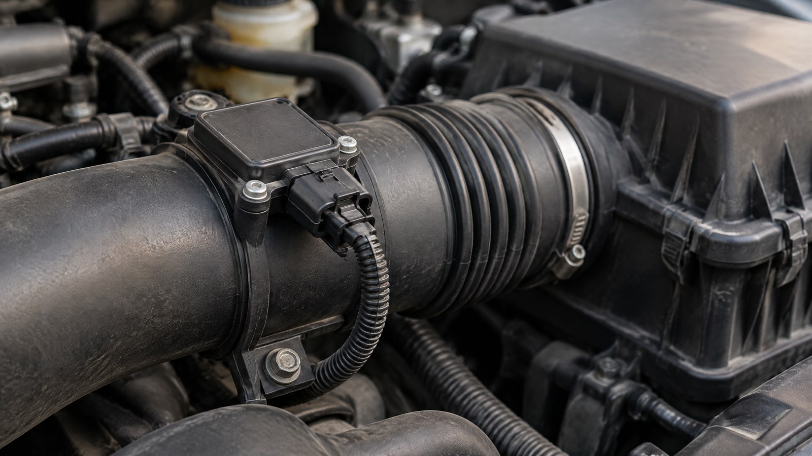
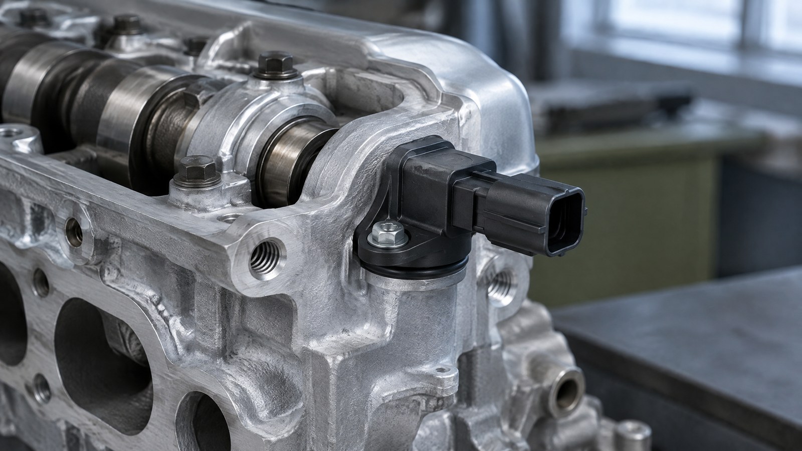
AI-generated editorial illustration of generic camshaft-position sensing hardware near an engine timing assembly, not a photograph of a tested product or an actual field measurement.
Phase is the distinguishing idea
The camshaft controls valve events and operates in step with the crankshaft. A crankshaft-position signal gives the controller a detailed reference for crank movement and speed, while the camshaft reference helps link that movement to the relevant valve-event sequence. In practical terms, the CMP input helps the controller distinguish the context of repeating crank positions rather than treating every similar angle as the same point in the engine cycle [1] [3].
This is why the sensor is best understood as a phase identifier. It contributes information about which part of the cycle the engine controller is seeing; it does not itself open a valve, create a spark or mechanically set engine timing. The controller combines its input with other vehicle information before directing the systems it manages.
Cam and crank information answer different parts of the question
Camshaft and crankshaft signals are complementary rather than interchangeable. Technical material from Snap-on describes the combined information as supporting engine-cycle position, cylinder identification and cam/crank synchronization [1]. Walker Products similarly describes the two inputs as position and speed data used by the engine control module for fuel-injection and ignition timing [2].
A useful mental model is that the crankshaft signal establishes the moving angular reference, while the camshaft signal adds the phase label that makes that reference meaningful for the valve and combustion sequence. That distinction keeps this article focused on engine coordination, rather than repeating a broad introduction to position sensors.
The sensing arrangement depends on the engine
Many CMP systems read a target feature that passes the sensor as the camshaft rotates. The target may be described as a reluctor, phonic wheel or another engineered reference feature, and the mounting location can vary with the engine layout [1] [2] [4].
The underlying sensing technology also varies. Snap-on describes inductive magnetic-pulse sensors that generate an analogue signal as a toothed target changes the magnetic field, and active Hall-effect sensors that switch a digital signal as the target passes [1]. The same source notes magneto-resistive sensors as another digital approach that can be especially sensitive to small magnetic-field changes. These are design families, not a rule for every vehicle; the exact pattern and controller expectations belong to the specific vehicle documentation.
Why Variable-Valve Systems Make Phase Information Meaningful
On engines equipped with variable valve timing, camshaft position information can form part of the feedback context for the control system. Wells Vehicle Electronics states that CMP data can be used for ignition timing, fuel-injection timing and variable-valve-timing operation where applicable [4]. The phrase “where applicable” matters: not every engine has the same valve-train design or the same variable-valve hardware.
A reference signal is not an adjustment mechanism
A camshaft position sensor measures and reports; it is not the component that physically changes a camshaft’s relationship to the engine. The engine controller uses sensor inputs to understand what is happening, then works within the design of the particular system. Treating the sensor as an adjustment device can obscure the more useful question: whether the controller has a reliable, vehicle-specific phase reference.
This distinction also avoids a common oversimplification. A discussion of variable-valve operation should not imply that every CMP concern is a variable-valve-system fault, or that every engine uses an identical strategy. The sensor’s role is informational, and its significance depends on the surrounding mechanical and electronic system.
More context can be necessary for a sound interpretation
A camshaft-related warning or stored record may concern the sensor circuit, the quality of a signal, the relationship between cam and crank signals, or another condition affecting the system. Walker Products explicitly labels generic code lists as general guides and advises vehicle-manufacturer guidance and professional diagnosis [2]. Snap-on likewise notes that a fault code records that a problem was detected but does not always identify the root cause [1].
For readers, the safe takeaway is that correlation matters. A qualified technician can interpret the relevant vehicle data in context rather than treating a generic label or a single symptom as confirmation that one part must be replaced.
What a Camshaft Position Sensor Reading Cannot Prove by Itself
A CMP signal is useful, but it is not a complete verdict on engine condition. Its meaning depends on the engine design, target feature, connections, controller logic and mechanical timing relationship. A reader should therefore separate the purpose of the sensor from any conclusion about the source of a vehicle problem.
A signal concern can have more than one cause
Manufacturer technical material identifies several influences that can affect the wider system. Wagner lists heat cycling, wiring or connector concerns, and dirt or water among possible reasons readings may be affected [3]. Snap-on also notes that trigger-wheel imperfections, mechanical wear, debris and contamination can affect some sensor arrangements [1].
Those categories do not diagnose any individual vehicle. They show why an apparently camshaft-related concern deserves a system-level assessment instead of an assumption that the sensor alone is responsible. Component location also varies: Wells lists possible locations including the cylinder head, timing cover and engine block, depending on design [4].
Familiar symptoms are not a component verdict
Hard starting, uneven running, loss of acceleration, stalling, reduced fuel economy and a warning light are commonly associated with engine-management concerns in general technical guidance [3] [4]. Yet Wagner emphasizes that such symptoms can be related to problems other than a faulty camshaft or crankshaft sensor [3]. They are reasons to seek assessment, not a reliable do-it-yourself identification method.
If a vehicle has unpredictable stalling, severe rough running or another condition that may affect road safety, it should be assessed promptly by a qualified professional. This educational article does not provide testing, wiring, timing or replacement instructions.
An India-Use Scenario: Context Before Conclusions
Indian owners may encounter a warning light or starting concern after conditions such as heavy rain, congested commuting or long periods of engine heat. Those circumstances do not establish a CMP fault. They simply make it sensible to record what occurred and to have a trained professional evaluate the vehicle-specific system rather than relying on a generic symptom list.
Hypothetical example: a concern after monsoon travel
Consider a hypothetical owner whose car develops an intermittent starting concern and an engine warning light after several wet commutes. Water exposure can affect sensor-system readings according to Wagner’s general guidance [3], but that fact does not show that water reached this vehicle’s CMP sensor, that the sensor failed or that it is the only relevant component. The responsible next step is professional assessment using the manufacturer’s information for that exact vehicle.
The useful information to share is the vehicle’s make, model, engine variant if known, when the concern started, whether it is intermittent and whether there were unusual drivability changes. This is observational context, not a diagnosis, and it helps avoid mistaking an environmental coincidence for proof of a failed part.
The owner’s role is observation, not calibration
A nonexpert can notice changes in starting, idling, warning indicators or drivability and describe them accurately. Interpreting cam/crank relationship data, signal quality or valve-timing context requires the correct equipment, reference information and training. No universal voltage, waveform, timing or fault-code threshold can responsibly be inferred from a general explainer.
Important Points / Key Information
The central idea is coordination. The CMP adds phase context to the crankshaft reference so the controller can relate piston movement, valve events and combustion scheduling in the manner designed for that engine. That role explains its importance without turning the sensor into a catch-all explanation for engine problems.
Key Takeaways
- A camshaft position sensor contributes engine-cycle phase information; it is not merely a generic speed sensor.
- The engine controller uses CMP information with crankshaft information to support cylinder identification and synchronization [1] [2].
- On compatible engines, CMP data can be relevant to variable-valve-timing operation, but the sensor does not mechanically adjust the valve train [4].
- A warning light, stored code or drivability symptom does not prove the sensor itself is faulty [1] [3].
- Vehicle-specific documentation and qualified interpretation are essential because layouts, signal types and control strategies vary.
Examples / Supporting Information
Source-grounded example: look beyond the named component
Snap-on describes a Chrysler 3.6L Pentastar example in which mechanical wear could create fine metal particles that accumulated on magnetic sensing components and interfered with accurate magnetic-field interpretation [1]. The teaching point is broader than that engine: replacing a named sensor may not resolve a repeated condition if the underlying cause is elsewhere in the system. This is an illustrative technical example, not a diagnosis of any vehicle and not a recommendation for a repair.
Comparing the two inputs without confusing their roles
The crankshaft-position input is commonly described as the controller’s reference for crank position and rotational speed, while the camshaft-position input adds the camshaft’s phase-related position information [2] [3]. Looking at only one input may not fully explain how the controller sees engine synchronization. That is why professional interpretation can consider the relationship between signals rather than assuming that one apparently related reading tells the whole story [1].
Conclusion
The camshaft position sensor is most clearly understood as the engine controller’s phase reference. Working alongside crankshaft information, it helps the controller place valve-related events and combustion decisions in the correct engine-cycle context, and it can matter to variable-valve systems where fitted. Because sensor signals, symptoms and stored records can be influenced by several system-level factors, this educational article should not be used as a substitute for vehicle-specific professional assessment.
How we checked thisSources (4)
We keep source links private so your reading stays on techduopulse. Each note names the publisher and document we checked.
Snap-on Diagnostics on cam/crank synchronization and signal types
Primary source · Phase identification; sensing arrangements; supporting exampleWalker Products on CMP/CKP coordination and application differences
Primary source · CMP and CKP roles; interpretation limitsWagner Brake on valve and piston coordination plus non-specific symptoms
Primary source · Phase context; limits of symptom-based inferenceWells Vehicle Electronics on CMP data and variable-valve applications
Primary source · Variable-valve systems and location variabilityOwner-approved educational sensor explainer; obsolete private-draft status removed without changing source-backed facts or professional safety boundaries. Original generic AI editorial illustration, not a product or field-test photograph.