
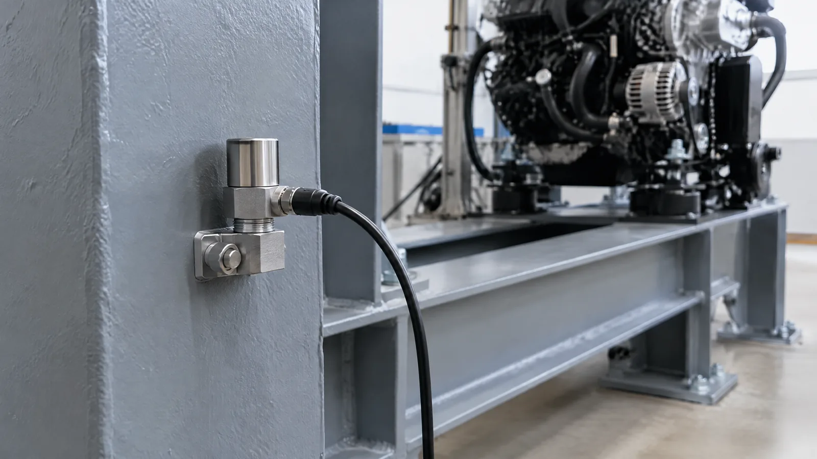
When an engine test shows a vibration spike, the useful question is not simply whether the rocket moved: engineers need to know where the motion occurred and how it changed over time. A rocket vibration sensor is usually an accelerometer that measures vibration-related acceleration on an engine, turbopump mounting point or nearby structure so a test team can examine dynamic behaviour.
This article is part of the computer hardware technology guide library.
Key takeaways
A rocket vibration sensor is an application of an accelerometer for observing dynamic motion during engine or structure tests. The physical sensor is only one part of the measurement chain.
- NASA Stennis says accelerometer data can support structural-model validation and turbopump-health monitoring.
- Piezoelectric charge-output accelerometers are common in the NASA Stennis hot-fire instrumentation example; IEPE and MEMS designs have different interfaces and operating characteristics.
- Mounting, cabling, signal conditioning, digitisation and analysis affect what the recorded vibration means.
- A vibration trace is test evidence, not by itself a diagnosis, flight-control command or safety guarantee.
What does a rocket vibration sensor measure?
The sensor measures acceleration that varies with time. In a rocket-engine test, that changing signal can show how an engine, turbopump support or structure responds to ignition, steady operation and other test events. The accelerometer does not directly measure turbopump efficiency, thrust or structural strength; those questions need other instruments and engineering models.
NASA Stennis places accelerometers in its high-speed data-acquisition group alongside strain gauges, dynamic-pressure sensors and microphones. That grouping matters because vibration is a dynamic signal: the time history and frequency content can be more informative than a single slow reading. The cited NASA system is a facility example, not a universal sampling specification.
How the measurement chain works
A physical accelerometer converts motion of its sensing element into an electrical output. A piezoelectric charge-output unit produces charge proportional to acceleration, commonly expressed in picoCoulombs per G in the NASA Stennis presentation. The charge then needs suitable signal conditioning, cabling and a digitiser before software can display or analyse a waveform.
An IEPE accelerometer includes electronics that convert charge to a higher-level voltage output, but it requires power through appropriate signal conditioning. A variable-capacitance MEMS accelerometer is a different technology and can provide a DC response down to 0 Hz. These options should not be treated as interchangeable simply because all are called accelerometers.
The final chain may include the sensor, mounting interface, cable, charge amplifier or IEPE conditioner, analogue-to-digital converter, time reference and analysis software. NASA notes that capacitance—much of it in cabling—can affect charge-to-voltage conversion in its charge-output setup, which is why calibration and installation details matter.
Why placement and environment matter
A sensor records motion at its own mounting point. A unit on a turbopump housing can see a different vibration signature from one on a test-stand frame or a nearby lightweight panel. The mounting stiffness, orientation, cable routing and local temperature all influence the usable measurement, so a reading cannot be moved from one location to another without considering the installation.
Rocket tests also span demanding environments. Kistler describes piezoelectric acceleration sensors for high-temperature and cryogenic applications, including accelerometers mounted close to a combustion chamber for combustion-instability measurement. Its cited page gives application examples reaching up to 550 °C for ultra-high-temperature accelerometers and down to -196 °C for cryogenic accelerometers and pressure sensors. Those are application ranges for particular sensor families, not a promise for every model.
Some hardware is external to the sensor itself. Brackets, washers, cables, charge converters, signal conditioners and DAQ channels may all be required, while a particular test article may use only some of them. Product choice and installation must follow the test facility’s qualified engineering process.
How engineers use vibration data in testing
NASA says accelerometer data can help validate structural models and monitor turbopump health. In plain terms, engineers can compare measured dynamic behaviour with an expected model or with appropriately comparable test records, while checking the timing and conditions of the test. The accelerometer supplies evidence; it does not decide on its own whether a turbopump is healthy.
Kistler presents vibration characterization alongside thrust and pressure measurement as part of rocket-engine testing. That wider context helps avoid a common mistake: interpreting one vibration channel as a complete picture of propulsion performance. Other sensors, test metadata and engineering review may be needed to understand a signal.
The NASA presentation mentions automatic termination when excess vibration levels are detected at its test facilities. This is a facility-specific safety and test-control capability. It should not be copied into a hobby project, treated as a universal threshold, or confused with a sensor’s own function.
Important limitations
The phrase rocket vibration sensor does not identify one standard component. Sensor type, range, bandwidth, temperature capability, sensitivity, axis count and output interface vary by model and application. A triaxial accelerometer measures three directions, but NASA notes that it still uses three digitiser channels in its example.
A raw waveform can be affected by mounting resonance, cable effects, electrical noise, temperature, cross-axis response, conditioning settings and sampling choices. Calibration checks help establish whether the measurement chain is behaving as expected, but calibration does not turn an isolated channel into a complete diagnosis.
For a beginner, the safe boundary is simple: treat this topic as measurement literacy. Do not use a consumer or improvised sensor reading to set propulsion limits, command an engine, trigger an abort, or claim that hardware is safe. Those decisions require qualified systems, procedures, instrumentation and review beyond this explainer.
FAQs
Is a rocket vibration sensor the same as a navigation accelerometer?
They can belong to the same broad accelerometer family, but the application is different. Navigation systems estimate vehicle motion for guidance or state estimation, while a vibration-monitoring installation is placed and specified to observe dynamic behaviour at an engine, turbopump or structure during testing.
Why are piezoelectric accelerometers common in rocket engine tests?
NASA Stennis describes piezoelectric charge-output accelerometers as its most common type in the cited hot-fire instrumentation example. They provide a dynamic acceleration signal and can suit hot installations, but they require compatible signal conditioning and calibration of the complete measurement chain.
Does an accelerometer measure turbopump health directly?
No. Its data can provide evidence about vibration patterns that engineers use when monitoring turbopump health. A health assessment also depends on sensor location, test conditions, other measurements, models and engineering interpretation.
What is the difference between charge-output, IEPE and MEMS accelerometers?
Charge-output piezoelectric units send a charge-related signal and need external conditioning. IEPE units include electronics and need power through their conditioner. Variable-capacitance MEMS units use a different sensing method and can measure down to DC. The suitable choice depends on the test environment and measurement requirements.
About the image
AI-generated editorial illustration; not an actual product or mission photograph.
Source notes
Reporting record
techduopulse stores source destinations privately. Public notes remain non-clickable so every visitor journey stays on this website.
Source note: NASA Stennis Space Center rocket-engine hot-fire sensor presentation
Primary source · Vibration measurements, turbopump-health monitoring, piezoelectric charge-output accelerometers, IEPE/MEMS distinctions and high-speed acquisitionSource note: Kistler rocket-engine testing measurement guidance
Primary source · Rocket vibration characterization, dynamic acceleration sensors, high-temperature and cryogenic application examples, and optional triaxial/DAQ componentsInitial 15 October 2026 India-facing application explainer. Distinguishes the rocket vibration sensor use case from the existing broad accelerometer guide, separates the physical accelerometer from conditioning and DAQ, and limits claims to NASA Stennis and Kistler evidence without vibration thresholds or DIY control advice.


