
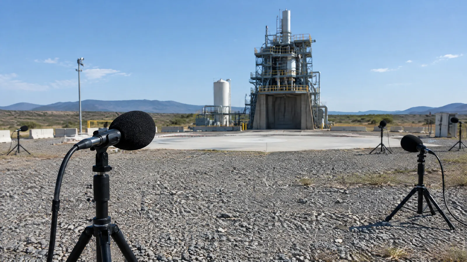
When a rocket-engine test stand sounds overwhelmingly loud, engineers still need to know which part is creating the strongest acoustic load rather than treating the whole test as one noise source. A rocket-test acoustic-pressure microphone array measures changing air pressure at many precisely arranged points, then combines those signals to show where the sound is coming from.
This article is part of the computer hardware technology guide library.
Key takeaways
This is specialist ground-test instrumentation for static fires and launch-pad measurements, not a universal onboard rocket sensor or a hobby microphone kit.
The documented NASA system used 70 piezo-resistive dynamic-pressure sensors on a custom open-frame dome, with cables, amplifiers and data equipment outside the harshest area.
The array does more than record loudness. Its timed multi-sensor data can be processed into directional noise maps that help identify likely sources such as a plume deflector or openings around a nozzle.
The exact sensor range, geometry, spacing and distance belong to the documented test setup; they should not be copied as general requirements for every rocket test.
- It measures acoustic pressure changes at multiple locations.
- It supports source localization through phased-array processing.
- It is a large, coordinated measurement system rather than one standalone microphone.
What does a rocket-test acoustic-pressure microphone array measure?
The physical sensing elements respond to fluctuations in air pressure caused by engine exhaust, plume interaction, structures and surrounding flow. Each channel produces a time-varying electrical signal. Looking at one channel can show that the environment is intense or that a frequency is present, but it cannot by itself say which part of a distant test stand produced the sound.
An array adds spatial information. Because the sensors occupy known positions, the measurement system can compare the arrival timing and phase of the same acoustic wave across the channels. Those differences help estimate the direction of the source and distinguish one region of a test stand from another.
That makes the array different from a basic sound-detection module. A hobby module may provide an analogue voltage or threshold trigger. A rocket-test array is designed around sensor matching, geometry, synchronized acquisition, environmental protection and later analysis.
How NASA’s documented RS-25 test array was arranged
NASA’s reported system was a custom phased array tested during a static firing of an RS-25 engine at the A-1 Test Stand at Stennis Space Center. It used 70 piezo-resistive dynamic-pressure sensors mounted on an open-frame dome about 10.5 feet in diameter. The dome was supported on a tall scaffold and pointed toward the test stand rather than being placed inside the engine hardware.
The published manuscript describes a designed sensor pattern intended to improve resolution over a stated 500 Hz to 2 kHz range and reduce sidelobes, which can appear as misleading secondary sources on a map. Twenty-four sensors were positioned on logarithmic spirals inside a base circle, while the remaining sensors were distributed through the planned arrangement on the curved structure.
The array’s support equipment was part of the measurement chain. A cable bundle ran roughly 200 feet to a weather-protected data-acquisition cabinet. The documented setup also used amplifiers and cameras, while an engine start-stop signal was recorded alongside microphone data so the acoustic record could be aligned with the test event.
| Part of the setup | Role | What it is not |
|---|---|---|
| Dynamic-pressure sensors | Convert local acoustic pressure changes into electrical signals | Not a complete source-localization system by themselves |
| Dome and sensor geometry | Give the channels known spatial relationships for phased processing | Not a universal layout for every test site |
| Cables, amplifiers and acquisition cabinet | Carry, condition and record the many sensor channels | Not additional acoustic sensing locations |
| Beamforming software | Combines the timed signals into directional or spatial noise maps | Not a physical microphone or camera |
How phased-array processing locates noise sources
A phased array tests possible source directions against the signals arriving at the sensors. If the timing and phase relationships for a direction fit the measured data, the processing reinforces that direction in the resulting map. Signals that do not fit can be reduced, although reflections, background noise and imperfect measurements can still complicate interpretation.
This process is commonly called beamforming. The NASA manuscript compares conventional and functional beamforming and reports that the latter produced smaller modeled spots in its example frequencies. The practical meaning is improved ability to separate nearby features in that study’s operating conditions, not a promise that every array will achieve the same resolution.
The output is therefore best understood as a noise-source map over a photographed or modeled view of the test stand. It can guide engineering attention toward a structure, opening or flow interaction. It does not mean that the array has photographed sound or that every bright region is automatically the only cause of the measured load.
What the static-fire measurement revealed
In NASA’s full-scale RS-25 test, the beamformed maps identified the plume deflector at the bottom of the engine as the primary reported noise source. Openings around the nozzle exit were also identified as sources, particularly at higher frequencies. This is useful because a test stand’s acoustic environment is produced by the engine, plume and surrounding structures together.
The array was positioned about 460 feet from the stand on a 50-foot scaffold. That distance and elevated view gave the sensors a broad line of sight while keeping the custom hardware outside the immediate engine area. The arrangement is evidence of how demanding the measurement problem is: the instrument must capture useful pressure signals across a large, energetic test environment without being treated as a small local sensor.
The cameras in the setup provided visible and infrared views for placing the acoustic maps into physical context. They were supporting instruments for interpretation, not replacements for the pressure sensors.
Limits and what the sensor is not
A rocket-test acoustic-pressure microphone array should not be described as a generic ‘rocket microphone’ that can be installed anywhere. Sensor type, pressure range, spacing, cable routing, shielding, calibration, sampling and structural placement depend on the test objective and environment. NASA’s reported 25-psia sensor range and 0–5 V full-scale output are details of listed sensors in that custom system, not universal specifications.
The array also does not directly provide a complete explanation of vehicle vibration, structural stress or payload safety. Acoustic measurements can inform those engineering questions, but they are one measurement stream among many. The documented work used phase testing and precise coordinate measurement because small channel or placement errors can affect a source map.
This is not a safe beginner build project. Rocket static fires involve hazardous propulsion, high temperatures, pressure, water-deluge systems and restricted test facilities. The useful lesson for students and general readers is how distributed sensing and signal processing turn a difficult acoustic environment into evidence that engineers can inspect, not how to approach an active test area.
Frequently asked questions
These answers refer to the NASA-documented phased-array application and should not be read as specifications for every commercial microphone or rocket test.
Is a rocket-test acoustic-pressure microphone array an onboard rocket sensor?
Usually no. The documented NASA array was specialist ground instrumentation placed near an engine test stand to measure and localize acoustic sources during a static firing. An onboard vehicle may use different sensors for its own flight measurements.
How many sensors did the NASA RS-25 test array use?
The reported custom array used 70 piezo-resistive dynamic-pressure sensors on an open-frame dome. That number belongs to the documented NASA design and is not a universal requirement.
Does the array only measure how loud the rocket is?
No. It records acoustic-pressure signals at known positions. Phased-array processing compares timing and phase across channels to create directional maps that can help locate noise sources, not merely report one overall loudness value.
Why are cameras included in the documented setup?
NASA used visible and infrared cameras to provide visual context for overlaying the beamformed acoustic maps. The cameras supported interpretation; the dynamic-pressure sensors supplied the acoustic measurements.
Can a hobby microphone module replace this type of array?
No. A hobby module may demonstrate sound detection, but it does not automatically provide the matched channels, controlled geometry, rugged installation, synchronized acquisition and beamforming workflow needed for a specialist rocket-test measurement.
About the image
AI-generated editorial illustration; not an actual product or mission photograph.
Source notes
Reporting record
techduopulse stores source destinations privately. Public notes remain non-clickable so every visitor journey stays on this website.
Source note: NASA technical record on the RS-25 test-stand microphone phased array
Primary source · 70-sensor array, dome, cable bundle, static-fire context and reported noise-source findingsSource note: NASA/AIAA manuscript describing array hardware, placement and beamforming
Primary source · Sensor layout, pressure-sensor details, phase testing, photogrammetry, 460-foot placement and processing limitsNew India-facing hardware explainer for a distinct rocket-test application. Separates physical dynamic-pressure sensors from the dome, cables, acquisition equipment, cameras and beamforming software; uses NASA’s RS-25 static-fire evidence; qualifies all model-specific dimensions and ranges; and avoids DIY propulsion or test-site instructions.


