
When a launch vehicle begins to climb, it is not enough for its avionics to know that the vehicle is moving forward; they also need to know whether it is turning and how quickly. A rocket gyroscope measures that angular rate, usually as one sensing element inside an inertial measurement unit (IMU), while the wider navigation system combines it with other measurements and algorithms.
This article is part of the computer hardware technology guide library.
Key takeaways
A launch-vehicle gyroscope reports rotation rate around one or more sensing axes; it does not measure position by itself.
An IMU combines gyroscopes with accelerometers and may include other instruments, depending on the design. An inertial navigation system (INS) adds processing that estimates position, velocity and orientation from the IMU and an initial state.
Bias, noise, temperature, vibration and integration over time can affect the result, so a gyro reading is one part of a validated avionics chain.
- Measures angular rate, not location
- Works as part of an IMU and larger navigation system
- Model-specific technologies and external aiding must not be treated as universal features
What does a rocket gyroscope measure?
A rocket gyroscope is an angular-rate sensor. It reports how quickly the vehicle rotates around its sensing axes, commonly expressed in degrees per second or radians per second. That signal helps avionics track changes in attitude, such as pitch, yaw or roll, but the sensor is not a complete navigation computer.
The physical sensor can use different technologies. A compact MEMS gyro uses vibrating microstructures and detects rotation-related Coriolis motion. Other inertial systems may use optical or resonator-based approaches. The application determines the required trade-offs among size, power, dynamic range, stability, environmental tolerance and cost; the phrase “rocket gyroscope” does not identify one universal component or accuracy level.
Where the gyroscope fits: sensor, IMU and INS
These three terms describe different layers. The gyroscope is the transducer that senses angular rate. An IMU is an instrument package that combines gyroscopes and accelerometers to provide raw inertial motion data. Some packages also include instruments such as inclinometers, but that is a design choice rather than a definition of every IMU.
An INS sits above the IMU. It uses the IMU’s angular-rate and acceleration data, an initial position and orientation, and processing algorithms to estimate the vehicle’s position, velocity and attitude as motion continues. Safran’s technical explanation describes the INS as a system built on IMU data, which is why “the rocket has a gyroscope” should not be treated as equivalent to “the rocket has an inertial navigation system.”
External inputs can also be available in a broader avionics architecture. GNSS aiding, timing references or other navigation observations may help bound an inertial estimate when the system is designed to use them. They are optional system-level components, not part of the gyroscope itself.
| Layer | What it does | What it is not |
|---|---|---|
| Gyroscope | Measures angular rate | Not a position solution |
| IMU | Packages gyroscopes and accelerometers for raw motion data | Not automatically a full INS |
| INS | Processes inertial data to estimate position, velocity and orientation | Not a single physical sensor |
Why rotation data matters during launch
A launch vehicle experiences changing motion and vibration, so its avionics need a time-ordered picture of how the vehicle is rotating. The gyroscope contributes the rotational part of that picture. Accelerometers contribute linear specific-force information. Processing the two together gives the navigation system more information than either sensor can provide alone.
The useful point for a beginner is that the gyro does not “see” the vehicle’s map location. It observes rotation. When a system combines that rate with acceleration data and an initial state, it can propagate an estimate of how the vehicle’s orientation and movement are changing. This is why manufacturer documentation describes IMUs as sources of raw motion data and INS units as the systems that calculate navigation states.
A gyro’s axes are aligned with the vehicle or its instrument frame through the avionics design. The navigation software must account for that frame, timing and alignment rather than treating an unlabeled sensor value as a universal direction. This is one reason the physical installation, calibration record and interface specification matter as much as the sensor name.
The signal is also time-dependent. A single angular-rate sample says little about the vehicle’s complete attitude. A sequence of samples, combined with acceleration data and a defined starting state, is what lets an INS maintain an evolving estimate. The quality of that estimate depends on the complete chain, not on a keyword such as “high precision” alone.
This article stays at the measurement and architecture level. It does not describe steering commands, trajectory design, propulsion, vehicle construction or safety-critical operating procedures.
Drift and other limits to read correctly
A gyroscope’s output is not perfectly stable. A small bias means the reported rate can be offset even when the vehicle is not rotating as assumed. Noise can make individual readings fluctuate. Temperature, vibration, shock, installation stresses and changes in scale factor can also affect the measurement. Safran identifies bias stability, angular random walk, data rate, dynamic range and environmental robustness as important IMU considerations.
The error matters because navigation software integrates measurements over time. A small rate error can accumulate into an orientation error, and that can influence later navigation estimates. Calibration and sensor fusion can compensate for some known behaviour, but they do not make every reading exact in every environment. A published specification for one model must therefore not be applied to all rocket gyroscopes.
For readers comparing technical descriptions, “accuracy” is not one number. Bias stability concerns longer-term output behaviour, while noise and angular random walk describe other parts of signal quality. Dynamic range concerns how much angular rate the sensor can represent. These terms should be read from the same model’s datasheet and test conditions; mixing figures from different instruments can create a false comparison.
Some high-performance systems use model-specific technologies. Safran describes its HRG-based systems as solid-state rotation sensors with no moving parts in the cited product context. That is useful evidence that more than one gyro technology exists; it is not proof that every launch vehicle uses HRG, MEMS or any other single design.
- Bias: a repeatable offset in the reported rate
- Noise: short-term variation in the signal
- Drift: accumulated orientation error when rate errors are integrated
- Environmental sensitivity: changes caused by heat, vibration, shock or installation
Frequently asked questions
Is a rocket gyroscope the same as an IMU?
No. A gyroscope is a sensor that measures angular rate. An IMU is a package that combines gyroscopes and accelerometers, and may include additional instruments depending on its design.
Can a gyroscope measure a launch vehicle’s position?
No, not by itself. It measures rotation rate. Position and velocity estimates require a wider system that processes gyroscope and acceleration data from a known starting state, with any additional aiding the design provides.
Does every launch vehicle use the same type of gyro?
No. Gyro technology depends on the vehicle and avionics requirements. MEMS, optical and resonator-based approaches are examples of different technology families, but a particular vehicle’s design must be established from its documentation.
Why can inertial navigation drift?
Inertial estimates integrate sensor measurements over time. Small bias, noise and environmental effects can therefore accumulate into errors in orientation, velocity or position. Calibration, fusion and system-level validation address these limits but do not remove them universally.
About the image
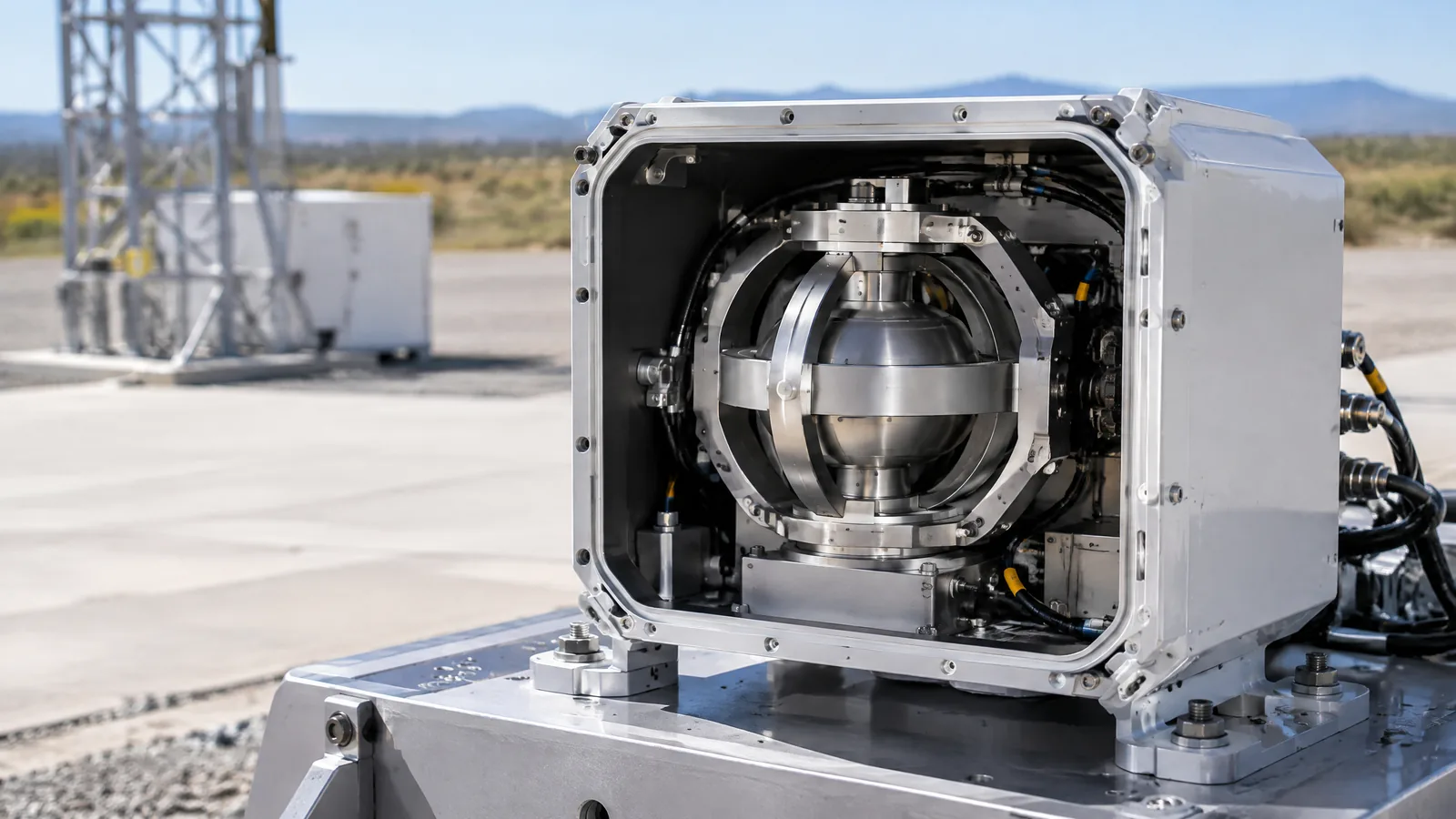
AI-generated editorial illustration; not an actual product or mission photograph.
Source notes
Reporting record
techduopulse stores source destinations privately. Public notes remain non-clickable so every visitor journey stays on this website.
Source note: Safran inertial measurement unit guidance
Primary source · Defines an IMU as combining accelerometer and gyroscope sensing; distinguishes angular velocity and linear acceleration; describes raw motion data, GPS-independent inertial…Source note: Safran Navigation & Timing — Inertial Navigation Systems
Context source · Defines an INS as a system that uses IMU data and algorithms to estimate position, velocity and orientation from a known starting state; identifies launch vehicles and…Source note: techduopulse — Gyroscope Explained: How It Works in Phones
Context source · Existing same-site guide establishes the broad definition of a gyroscope as an angular-velocity sensor and distinguishes it from an accelerometer; this new page applies that…Created a distinct launch-vehicle application explainer rather than duplicating the existing phone-focused gyroscope guide. Added clear sensor/IMU/INS boundaries, optional and model-specific technology caveats, drift limitations, civil technical scope, and source-backed FAQs.


