
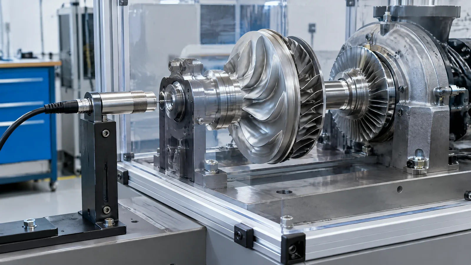
When a rocket-engine turbopump spins at high speed, engineers need to know whether its shaft is moving away from its intended centreline or along its axis without putting a contact probe into the rotating assembly. A noncontact inductive turbopump shaft-displacement sensor measures the changing gap to a conductive shaft target, turning radial or axial movement into an electrical signal for development and test instrumentation.
This article is part of the computer hardware technology guide library.
Key takeaways
This is a specialist displacement measurement arrangement, not a general-purpose proximity switch found in every launch vehicle.
An inductive probe observes how a conductive metal target changes an alternating electromagnetic field; the electronics then condition that change into a displacement signal.
The measurement can be arranged for radial shaft motion, axial shaft motion, or both, but the probe geometry and signal chain must match the measurement direction.
Cryogenic temperature, nearby conductive structures, target material, crosstalk and calibration can change the reading. A NASA/Aerojet report on a related capacitive prototype recorded a low-temperature shift, so its evidence should not be confused with proof of a universal inductive design.
- Use the sensor as an instrumentation element for understanding turbopump dynamics, not as a stand-alone safety decision.
- Treat probe, target, cable, driver and acquisition electronics as one calibrated measurement chain.
What does a turbopump shaft-displacement sensor measure?
A turbopump shaft-displacement sensor measures the shaft’s position relative to a fixed probe. In a radial arrangement, the instrument observes movement toward or away from the probe as the shaft rotates. In an axial arrangement, it observes movement along the shaft’s length. The output is therefore about relative position or motion at the measurement location, not a complete diagnosis of the engine.
This matters because a high-speed turbopump is a rotating machine with tight clearances and changing loads. During development testing, displacement data can be recorded with other measurements to help engineers study internal dynamics and correlate changes with operating conditions. The NASA Technical Reports Server record for NASA CR-182279 describes this exact broader need: measuring axial and radial displacement of turbomachinery shafts for rocket-engine control and health-monitoring work.
The sensor is external to the rotating target in the sense that it does not need to touch the shaft. That avoids a sliding contact at the sensing point, but it does not remove the need for careful mechanical placement, thermal design, electrical conditioning and calibration.
How the noncontact inductive measurement works
An inductive displacement probe creates an alternating electromagnetic field near its sensing face. When a conductive shaft target enters that field or changes its distance from the probe, eddy-current effects alter the probe’s electrical behaviour. A driver and signal-conditioning circuit interpret that change and provide a voltage, current or digitised value that represents gap over the calibrated operating range.
The word displacement is important. A basic inductive proximity switch may only report that a metal object crossed a threshold. A displacement instrument is intended to preserve more information about the changing gap, so its probe, oscillator or driver, calibration, bandwidth and data-acquisition path must be designed for that purpose. A generic industrial proximity switch should not automatically be described as a turbopump shaft-displacement instrument.
The shaft target also matters. Conductivity, geometry, surface condition and the presence of nearby metal can affect the field. The physical sensor is only one part of the system; the target, mounting structure, cable routing, electronics and calibration reference all influence what the recorded signal means.
Radial and axial shaft measurement are different jobs
Radial displacement describes movement across the shaft’s centreline. A probe positioned beside the shaft can observe a changing lateral gap. Engineers may use more than one measurement direction when they need to understand orbit-like movement or compare motion at different points, but the number and arrangement of probes are application-specific.
Axial displacement describes movement along the shaft’s centreline. A probe facing an appropriate end feature or target surface can observe that change. The target geometry and reference surface must remain suitable over the measurement range; a probe aimed at the side of a shaft cannot simply be treated as an axial instrument.
NASA CR-182279 investigated a related miniature multifunction capacitive sensor intended to sense axial displacement, radial displacement and speed in turbomachinery. That report is useful evidence for the measurement problem and the value of reduced housing penetration, but its detailed prototype was capacitive. It does not establish that an inductive probe and a capacitive probe have identical temperature behaviour, calibration or performance.
| Measurement | What changes at the probe | What must be matched |
|---|---|---|
| Radial displacement | The lateral gap between the probe and a conductive shaft target changes. | Probe location, shaft geometry, nearby metal and the required measurement direction. |
| Axial displacement | The gap to an axial reference feature changes along the shaft centreline. | End-target geometry, reference surface, probe facing direction and usable range. |
| Speed or phase-related observation | A repeating target feature or changing signal can provide timing information when the design supports it. | Target pattern, bandwidth, signal conditioning and separate validation of the speed measurement. |
Why cryogenic rocket-engine conditions are difficult
A cryogenic test environment changes more than the shaft temperature. Probe materials, reference components, insulation, cable connections, condensation and nearby structures can all affect the electrical relationship that was calibrated at a warmer condition. The measured shift may therefore reflect the complete sensor assembly rather than only real shaft motion.
The NASA/Aerojet report tested a related capacitive probe at liquid-nitrogen temperature and recorded an indicated displacement shift larger than expected from the change in dielectric environment. The report discusses possible contributions from reference-capacitor instability and leakage-capacitance changes linked to condensation or material behaviour, then recommends probe and signal-conditioning improvements. This is a useful warning about cryogenic instrumentation, not a numerical performance claim for every inductive sensor.
For that reason, a test team has to define the temperature range, target material, mounting condition and calibration reference for the actual instrument. Nearby conductive hardware and multiple probes can also introduce crosstalk or altered field conditions. A result that looks like shaft movement should be interpreted with the rest of the measurement chain and test record.
What belongs in the measurement chain?
The physical probe is the visible part of the system, but a useful displacement record normally depends on several coordinated elements. The probe and conductive target create the sensing interaction. A driver excites and reads the probe. Signal conditioning converts the raw electrical change into a usable channel. Cabling, shielding, acquisition hardware, timing and calibration determine how that channel is recorded and compared with other measurements.
Some components are optional or model-specific. A particular system may use a dedicated driver, differential acquisition, temperature monitoring, more than one probe, or a reference target. None of those should be treated as mandatory features of every inductive displacement sensor. Likewise, a thermocouple measures temperature; it is an external instrument used to characterise the test condition, not the displacement sensor itself.
The NASA report describes a clamp fixture, a Type T thermocouple, liquid nitrogen, a digital thermometer, a displacement console and a voltmeter in its own experimental setup. Those details show how one investigation characterised a related capacitive sensor. They are not a universal wiring diagram or a safe recipe for building a rocket-engine test.
Limits and responsible interpretation
A noncontact reading is not automatically a direct measurement of shaft stress, bearing health or engine safety. It reports the calibrated relationship between probe signal and target gap at the measurement location. Converting that signal into an engineering conclusion requires knowledge of the target, installation, dynamic response, temperature and other relevant channels.
The sensor is also not automatically flight-qualified because a research report discusses rocket-engine applications. The cited NASA document recommends further development for low-temperature performance, reliability and a flight-type signal-conditioning unit. That wording is a reminder to distinguish a development instrument, a test article and a qualified flight component.
For beginner readers, the practical lesson is simple: ask what is actually being measured, in which direction, against which target, under which calibration condition. Then check whether the source supports the claimed operating environment. Avoid borrowing specifications from a different sensing physics or from a different probe model.
Is a turbopump shaft-displacement sensor the same as a normal inductive proximity switch?
No. Both can use electromagnetic interaction with a conductive metal target, but a proximity switch commonly produces a thresholded detection output. A displacement instrument is intended to measure changing gap over a calibrated range and needs a suitable probe, driver, conditioning chain and installation.
What is the difference between radial and axial turbopump shaft displacement?
Radial displacement is movement across the shaft centreline, while axial displacement is movement along it. The probe direction and target geometry must match the measurement, so a side-facing radial arrangement cannot simply be reused as an axial measurement.
Can an inductive sensor measure a cryogenic turbopump shaft directly?
It may be considered for specialist development instrumentation, but suitability depends on the exact probe, target, temperature range, mounting, electronics and calibration. The NASA report supplied for this topic documents cryogenic shifts in a related capacitive prototype, so it supports caution rather than a universal inductive performance claim.
Does the sensor measure shaft speed as well as displacement?
Not automatically. Some multifunction turbomachinery instruments can derive speed from a suitable target pattern or signal, and the cited NASA report describes a related capacitive probe sensing speed as well as displacement. An inductive displacement channel should not be advertised as a speed sensor unless its design and documentation support that function.
About the image
AI-generated editorial illustration; not an actual product or mission photograph.
Source notes
Reporting record
techduopulse stores source destinations privately. Public notes remain non-clickable so every visitor journey stays on this website.
Source note: NASA Technical Reports Server report record
Primary source · Report identity, rocket-engine turbomachinery scope, axial/radial displacement and survey of sensing approachesSource note: NASA/Aerojet technical report PDF
Primary source · High-speed shaft-displacement task, capacitive prototype distinction, cryogenic shift, test setup and signal-conditioning recommendationsInitial 15 October 2026 India-facing application explainer. Creates a distinct page rather than duplicating the broad proximity-sensor or flight-technology guides; explains the inductive sensor concept and radial/axial measurement while carefully separating the cited NASA report’s related capacitive prototype from the target inductive application. Includes cryogenic limitations, model-specific/external instrumentation distinctions, non-safety framing and no unsupported performance claims.


