
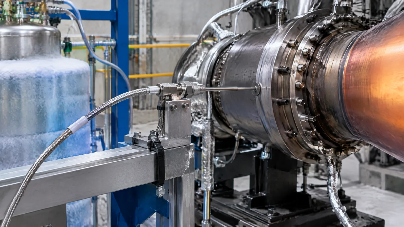
A temperature trace in a rocket propulsion test is only useful when the probe, cable, electronics and installation describe the intended location rather than a wiring artefact. A thermocouple temperature probe measures temperature through a small thermoelectric voltage from two dissimilar metals; in a hot-fire or cryogenic test, the complete measurement chain must be matched to the test environment and verified as a system.
This article is part of the computer hardware technology guide library.
What a thermocouple temperature probe measures in a rocket test
A thermocouple is a junction of two dissimilar metals. When the measuring junction and reference junction are at different temperatures, the sensor produces a small thermoelectric voltage. The instrumentation system interprets that voltage using the applicable thermocouple relationship and reference-junction information. It does not directly output a universal absolute temperature from the probe alone.
In propulsion testing, the probe may be placed at a hot or cryogenic location in a test article, feed system, stand component or other approved measurement point. The exact location and expected conditions come from the test specification. A thermocouple label such as E-type or K-type identifies a sensor family; it does not by itself establish the allowable installation, accuracy or temperature target for a particular test.
- Sensing junction: the point that responds to the local thermal condition.
- Thermocouple cable: conductors that preserve the intended thermoelectric signal until the transition point.
- Reference and transition measurement: information needed when the thermocouple wiring changes to ordinary copper.
- Signal conditioning and data acquisition: electronics that receive the millivolt-level signal, convert it and timestamp the result.
- Engineering-unit conversion: software or instrumentation logic that turns the measured signal into a temperature value.
How rocket hot-fire and cryogenic test installations differ
NASA Stennis Space Center’s rocket-engine hot-fire instrumentation presentation gives a concrete example of application-specific selection: it identifies E-type thermocouples for cryogenic-temperature applications and K-type thermocouples for hot-temperature applications. The presentation also describes probes in different lengths and thicknesses, with installation hardware selected for the required length. These examples show why a probe should be chosen from the measurement requirement, not from a generic temperature-sensor listing.
Mechanical placement matters as much as the electrical type. NASA notes that critical applications may need protuberance analysis, because a probe and its fitting can alter the local geometry or interact with the surrounding flow. The probe must also survive the environment specified for the test, including thermal cycling, vibration, cleanliness requirements and the details of its mounting. These are controlled test-engineering decisions, not suitable areas for improvised propulsion hardware.
| Measurement context | What the probe system must address | What not to assume |
|---|---|---|
| Hot test location | Probe family, junction construction, heat exposure, mounting and signal noise | A K-type label alone guarantees the required result |
| Cryogenic test location | Low-temperature response, cable and transition behaviour, cleanliness and installation limits | A room-temperature calibration or generic module specification transfers unchanged |
| Long cable run | Correct thermocouple extension wiring, transition/reference handling and signal conditioning | Ordinary copper wire can simply replace thermocouple cable anywhere |
Thermocouple versus RTD in propulsion-test instrumentation
Thermocouples and resistance temperature detectors (RTDs) can appear in the same rocket-test data-acquisition system, but they measure temperature through different electrical properties. A thermocouple produces a small voltage; an RTD uses the predictable change in resistance of its sensing element. The better choice depends on the required range, stability, installation, response, wiring and calibration method.
The NASA Stennis presentation describes thermocouples as relatively inexpensive in its stated context, while noting concerns such as low-temperature scaling and noise when a tip junction is grounded. It describes an RTD signal path using a constant current and sensor calibration coefficients, and presents RTDs as more accurate and rugged in that facility’s example, with higher procurement cost. Those observations are context-specific rather than a universal ranking of sensor types.
For a beginner, the useful distinction is simple: a thermocouple is often attractive when a rugged, application-matched probe and broad thermal capability are needed; an RTD may be preferred when a calibrated resistance measurement and repeatability are more important. Neither option removes the need to design and verify the complete measurement chain.
Why calibration includes more than the probe
A thermocouple system can be wrong even when the junction itself is intact. The measured voltage is small, and errors can enter through the thermocouple curve, reference-junction treatment, cable transition, amplifier, analogue-to-digital conversion, grounding, noise, software scaling or physical placement. NASA Stennis describes using thermocouple curves for engineering-unit conversion and voltage substitution to verify the amplifier and signal-conditioning operation in its facility practice.
This is different from claiming that every probe must be laboratory-calibrated in the same way. The appropriate method depends on the facility procedure, sensor documentation and test requirements. Calibration and compensation should be planned early, as NASA’s launch-vehicle instrumentation guidance recommends. The same guidance warns that long-term drift and software-based correction can add uncertainty if the reference is not sufficiently stable.
The practical takeaway is to retain the sensor identity, applicable calibration information, wiring configuration, signal-conditioning settings and verification record together. A displayed number without that context is not enough evidence for a critical test decision.
- Confirm the sensor family and the engineering-unit conversion used by the acquisition system.
- Check the transition from thermocouple cable to copper and the reference-junction measurement arrangement.
- Verify the signal-conditioning path with the facility-approved method before relying on the data.
- Record mounting, cable routing, grounding and environmental conditions that can affect the reading.
- Treat changes to a qualified installation as configuration changes requiring the responsible test organisation’s review.
Installation and reliability limits to understand
NASA’s launch-vehicle instrumentation lesson treats the sensor as part of a larger engineered system. It calls for controlled manufacturing and routing, inspection, protection from contamination, attention to insulation and wiring fatigue, and comprehensive test and verification plans. It also describes analysis, laboratory verification and hot-fire testing as possible parts of verifying instrumentation changes on a selected vehicle, propulsion system or component.
That context matters because a thermocouple is not automatically a control sensor, a safety interlock or a flight-qualified component. A temperature trace may be an open-loop observation, while a transducer used in a closed-loop control function has more severe failure consequences. Selection, installation and use in real propulsion systems belong to qualified organisations following their applicable requirements. This article explains the measurement concept; it is not a build, test-stand or engine-control procedure.
Key takeaways
A rocket engine thermocouple measures temperature through a thermoelectric voltage, but the reading depends on the junction, cable, reference handling, conditioning and conversion together.
NASA Stennis examples distinguish E-type thermocouples for cryogenic applications and K-type thermocouples for hot applications; those examples do not replace the governing test specification.
Thermocouples and RTDs have different signal paths and trade-offs. The right choice depends on the required conditions and verification plan, not a generic accuracy claim.
Calibration and installation records are part of measurement confidence, especially when cable transitions, noise, drift or configuration changes are involved.
Frequently asked questions
What does a thermocouple temperature probe measure in a rocket test?
It measures the thermal condition at its sensing junction by producing a thermoelectric voltage related to the temperature difference between the measuring and reference junctions. The acquisition system then applies the relevant reference handling and conversion to report temperature.
Which thermocouple type is used for rocket engine tests?
The type depends on the specified environment and installation. NASA Stennis’s presentation gives E-type examples for cryogenic-temperature applications and K-type examples for hot-temperature applications. A facility’s approved sensor and test specification take priority over a general rule.
Is an RTD better than a thermocouple for propulsion testing?
Not universally. An RTD measures resistance and can be selected when calibrated stability and repeatability are priorities; a thermocouple produces a voltage and may suit a different thermal or mechanical requirement. Compare the complete signal path, range, installation and verification method for the specific test.
Why does thermocouple wiring matter?
Thermocouple conductors and the transition to copper affect the reference relationship and the measured millivolt signal. Cable routing, grounding, electrical noise and signal conditioning can also change the reported value, so wiring is part of the measurement design rather than a minor accessory.
Can I use this information to build a rocket test setup?
No. The article is an educational explanation of instrumentation concepts. Hot-fire, cryogenic and propulsion-control work requires qualified personnel, approved hardware, formal hazard controls and the applicable facility and engineering procedures.
About the image
AI-generated editorial illustration; not an actual product or mission photograph.
Source notes
Reporting record
techduopulse stores source destinations privately. Public notes remain non-clickable so every visitor journey stays on this website.
Source note: NASA Stennis Space Center rocket-engine hot-fire sensor presentation
Primary source · E-type and K-type thermocouple application examples; probe dimensions and fittings; cable transition, millivolt signal conditioning, thermocouple curves and…Source note: NASA launch-vehicle instrumentation design and installation lesson
Primary source · Integrated sensor-system design; calibration and compensation planning; contamination, wiring and vibration controls; verification of changes; drift and open-loop/closed-loop…Initial new application page for rocket propulsion-test thermocouple instrumentation. It extends the site’s broad temperature-sensor coverage with NASA-sourced hot-fire and cryogenic examples, separates thermocouple elements from cable, conditioning and acquisition equipment, compares RTD signal paths without universal rankings, and includes calibration, installation and safety boundaries without DIY propulsion instructions or unsupported temperature targets.


