
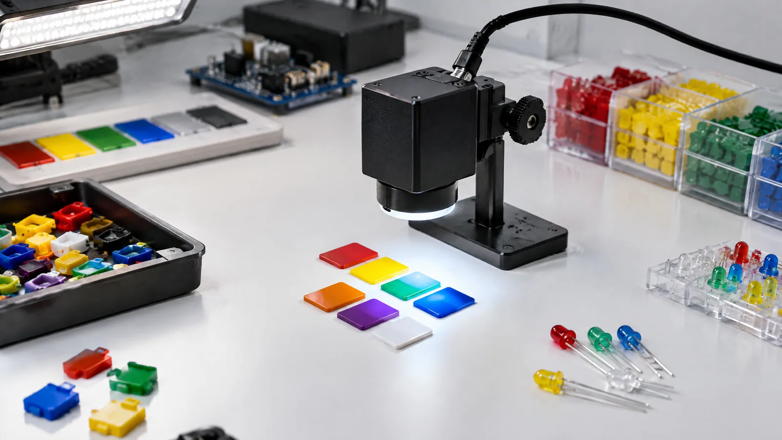
A red, green or blue part can look different when the lamp, distance or background changes, so a quick sensor reading may give a surprising result. An RGB/XYZ color sensor measures filtered light channels; with a fixed setup and a reference calibration, a controller can use those readings to compare colours or sort a simple set of parts.
This article is part of the computer hardware technology guide library.
Key takeaways
- An RGB/XYZ color sensor measures channel-specific light, not a camera image or a universal human-perception judgement.
- RGB channels are useful for practical color comparison; XYZ channels can support tristimulus measurement and chromaticity calculations when the device and software support them.
- Illuminant, distance, angle, target surface, filters and ambient light all affect the result.
- A reliable beginner project needs a repeatable fixture and reference samples before choosing classification thresholds.
What does an RGB/XYZ color sensor measure?
A color sensor uses photosensitive elements behind optical filters. The filters make different channels respond more strongly to selected parts of the incoming spectrum. An RGB device reports red, green and blue-related responses; an XYZ device is designed around tristimulus measurements and may support xy chromaticity coordinates in the CIE 1931 color system. The exact channel curves and output format depend on the component or module.
This is different from a camera. A camera records an array of pixels and can form an image. A color sensor normally reports a small set of channel values from the light reaching its aperture. It can help a controller decide that two samples are similar under the test conditions, but it does not know what a person would call a colour in every room or under every lamp.
Many integrated parts also include optical filtering to reduce unwanted infrared response. Some specific models add a clear channel, an IR channel, a light source, flicker detection or an I2C interface. Treat those as model-specific features: check the chosen datasheet instead of assuming that every RGB/XYZ breakout includes them.
RGB versus XYZ: choose the output for the job
RGB sensing is a practical starting point for a project that compares coloured parts or checks whether an LED is emitting roughly the expected colour. A microcontroller can read the three channels and compare their relative pattern after the setup has been calibrated. The comparison is application-specific, not a universal colour name.
XYZ sensing is useful when the system needs a tristimulus-style colour representation or chromaticity calculations. It can support more formal colour measurement, but the sensor, optical path, software conversion and calibration target still determine what the numbers mean. A label such as XYZ does not remove the need to control the light source and geometry.
For a small teaching project, use RGB when the question is ‘does this sample match my reference under this lamp?’ Consider XYZ when you specifically need chromaticity or a measurement workflow documented by the device maker. Correlated color temperature is an estimate of the colour appearance of a light source; it is not the same as measuring the colour of an opaque object.
| Output | Useful for | Watch for |
|---|---|---|
| RGB | Relative colour comparison, LED checks and simple sorting | Channel response, infrared leakage and lamp changes |
| XYZ | Tristimulus and chromaticity-oriented measurement | Device curves, conversion method and calibration reference |
| Clear or IR (model-specific) | Ambient-light context or infrared-aware analysis | Not present on every sensor; interpret with the datasheet |
A calibrated color sensor project for coloured parts
The physical sensor is only one part of the measurement chain. A typical learning setup can use an RGB or XYZ breakout, a microcontroller, a fixed matte background, a repeatable holder and a serial monitor. A controlled lamp may be useful, but it is an external project component rather than part of the sensing element. Keep the target at the same distance and angle, block stray light, and avoid letting the sensor’s own light source illuminate some samples but not others.
Start by recording readings from reference pieces that represent the categories you want to distinguish. Take several readings without moving the fixture and look for the natural spread in each channel. Then test new pieces under the same conditions. A simple classifier can compare the new reading with reference ranges or a distance in normalized channel space. Use thresholds learned from your own setup; do not copy a number from a different module, lamp or enclosure.
If the project uses a sensor with an integrated LED or an external LED, keep its drive level and timing consistent. If it uses ambient light, document the lamp and room conditions. A white or grey reference can help reveal drift, but it does not automatically turn an inexpensive module into a calibrated instrument. Production or safety-relevant sorting needs appropriate engineering validation rather than a hobby threshold alone.
- Fix the sensor-to-target distance and viewing angle.
- Use the same illumination and background during reference and test readings.
- Record channel values, not only a final colour label.
- Recheck the references when the enclosure, lamp or target material changes.
Why readings change even when the colour looks the same
A sensor responds to the light that reaches it, so the illuminant matters. Daylight, a white LED and a fluorescent source can produce different channel ratios when reflected from the same object. Distance and angle change the amount of received light; glossy surfaces add reflections; a nearby coloured wall can add reflected light. The cover, aperture and optical filters also shape the result.
Photodiode behaviour provides the underlying reason for this sensitivity. A photodiode can be modelled as a diode with a light-dependent current source, and its wavelength response depends on the device material. Integrated color sensors combine filtered photodiodes and electronics, but they still inherit the limits of their spectral response and optical geometry.
Common limitations and honest interpretations
Do not describe an RGB/XYZ reading as a universal colour truth. It is a measurement produced by one sensor, one optical path and one set of lighting conditions. Two sensors with different filter curves can report different values for the same sample. A color classification can therefore be repeatable in its intended fixture without being portable to another fixture.
Do not confuse optional modules with the physical sensor. A breakout board may add a regulator, connector, microcontroller library or LED. A calibration card, integrating enclosure, reference meter or stable light source is external equipment. A product may expose I2C or offer onboard conversion, but that is not guaranteed across the RGB/XYZ family.
For a classroom or maker demonstration, the safest claim is narrow: under the documented lamp, distance and fixture, the readings separate the chosen reference samples. If the application needs absolute color matching, chromaticity reporting or color-temperature measurement, use the component documentation and a calibration procedure appropriate to that requirement.
RGB/XYZ color sensor FAQs
Can an RGB color sensor work with Arduino?
Yes, if the selected module provides a compatible analogue or digital interface and the Arduino-compatible controller can read it. The program still needs a documented setup and locally measured references; a library does not create universal colour accuracy.
Is an RGB/XYZ color sensor a camera?
No. It normally measures a small set of filtered light channels rather than forming an image. It can support comparison or classification, but it cannot replace a camera for spatial detail.
Can a color sensor sort red, green and blue parts?
It can support a simple sorting demonstration when the parts, lighting, distance and background are controlled. Calibrate with representative samples and expect to retest if the lamp, enclosure or surface finish changes.
What is an XYZ color sensor used for?
An XYZ color sensor can be used for tristimulus-oriented measurement and chromaticity calculations when its channel responses and software support that workflow. The result still depends on optical geometry and calibration.
Does a color sensor measure color temperature?
Some color-sensing systems estimate correlated color temperature from the light source, but this is different from measuring an opaque object’s colour. Check the chosen device and software documentation before making that interpretation.
About the image
AI-generated editorial illustration; not an actual product or mission photograph.
Source notes
Reporting record
techduopulse stores source destinations privately. Public notes remain non-clickable so every visitor journey stays on this website.
Source note: ams OSRAM — Ambient light, color, spectral & proximity sensors
Context source · RGB and XYZ sensor families, CIE 1931 xy chromaticity, IR-blocking filters, color and spectral applications.Source note: Analog Devices — Light Sensor glossary
Context source · Photodetector definition and distinctions among photodiodes, photoresistors, phototransistors and photovoltaic sensors.Source note: Analog Devices University — Light Sensors and Photodiodes
Context source · Photodiode light-dependent current model, wavelength dependence, photovoltaic and photoconductive modes, and measurement/calibration considerations.Source note: Texas Instruments — Light sensors overview
Context source · Integrated visible/IR/XYZ/RGB sensing, spectral matching, color adjustment, color matching, field-of-view and calibration resources.Created a distinct application page because the existing light-sensor guide covers broad photodetector basics but not an RGB/XYZ color-measurement workflow. Added calibrated LED/part comparison guidance, model-specific component boundaries, limitations and FAQs grounded in four supplied technical sources.


