
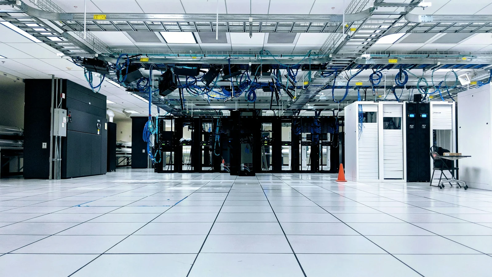
Air cooling removes heat by moving air across server components and carrying the warm exhaust to a cooling system. AI does not change that process, but powerful accelerators concentrate more heat into the equipment: NVIDIA specifies up to 14.3 kW for one eight-GPU DGX B200 system, while its DGX GB rack documentation describes approximately 120 kW per rack. These are product-specific figures, not typical consumption for every AI installation. [1] [2]
This guide explains the heat path, why airflow and pressure matter, and where liquid-assisted designs become useful. It includes a clearly labelled 100 kW calculation, separates chip cooling from outdoor heat rejection, and explains why Indian facilities need site-specific climate and water planning. Air is not obsolete, and liquid cooling is not a way to make heat disappear.
Show less
On this page 12 sections
- Key Takeaways
- How air cooling carries heat out of a data centre
- CRAC and CRAH: what changes inside the room cooling unit?
- Why AI hardware makes air cooling more demanding
- Why more airflow is not always a practical answer
- The 100 kW airflow calculation, explained
- Direct-to-chip, immersion and rear-door cooling do different jobs
- What India-focused cooling discussions need to include
- Important Points / Key Information
- Examples / Supporting Information
- Common questions about AI data-centre cooling
- Conclusion
Part of our cloud infrastructure technology guide library
Key Takeaways
- Cooling must move heat from the chip all the way outside the facility; a rack upgrade does not remove the final heat-rejection requirement.
- Air cooling has no universal rack-power ceiling. Hardware, chip heat flux, airflow, pressure and inlet conditions govern the result.
- The 100 kW examples explain flow, not installation capacity: circulating liquid volume is not water consumption.
- Liquid-cooled CPUs and GPUs can still require air for other components. Climate and whole-system efficiency matter.
How air cooling carries heat out of a data centre
Cooling has two distinct jobs: collect heat from IT hardware, then discharge it outside the building. A heat sink and a room cooling unit address different steps. Understanding the complete route prevents a common mistake—counting a rack cooling upgrade as extra capacity in a facility whose final heat-rejection system is already constrained. The US Department of Energy illustrates this chain using air-cooled racks, chilled-water circuits, a chiller and an evaporative cooling tower. [5]
In a common front-to-back rack server, heat travels from a processor through its package and thermal interface into a heat sink. Fans move air through the fins, and that air leaves the chassis warmer than it entered. A room or in-row cooling unit transfers the heat away from the returning air. The particular equipment decides how that heat finally reaches the outside environment; a raised floor is one distribution option, not a requirement. [5] [6]
Why cold and hot aisles need separation
A cold aisle serves server intakes; a hot aisle receives exhaust. Containment, blanking panels and sealed openings help prevent the two streams mixing. Otherwise, some equipment can draw hot exhaust back into its intake while some supplied cooling air bypasses the servers. A low average room temperature does not rule out a hot inlet at one rack. [5] [6]
The practical objective is useful airflow through the equipment, not simply a larger fan setting. Available cooling capacity and correctly delivered cooling capacity are different things. Obstructed paths, leaks and unbalanced distribution can make one rack struggle while nearby cooling capacity remains underused. [6]
CRAC and CRAH: what changes inside the room cooling unit?
A computer room air conditioner, or CRAC, typically uses direct-expansion refrigerant cooling, with a compressor within or associated with its cooling system. A computer room air handler, or CRAH, typically passes room air across a chilled-water coil connected to a central plant. Both move and condition air; the name identifies a different cooling arrangement, not a universal performance ranking. Some CRAC products also have additional chilled-water coils. [6]
A CRAH room unit normally has no refrigeration compressor of its own. That does not mean the facility is compressor-free: the central chiller may still use one. Comparing energy use requires the complete system—fans, pumps, refrigeration, heat rejection and operating conditions. A large chilled-water installation can be efficient, but it is not automatically better than every DX system in every climate or at every load. [4] [6]
Why AI hardware makes air cooling more demanding
For cooling calculations, essentially all electrical input to IT equipment eventually becomes heat. Accelerator utilisation, power limits and workload patterns affect the actual load, so maximum system power must not be presented as a measured continuous average. Training can sustain heavy processing; inference can also be intensive, but not every AI server runs permanently at full power. [1]
Two limits matter at the same time. Rack power describes the total heat to remove. Chip heat flux describes how tightly part of that heat is concentrated over a surface area. Equipment with the same total power can therefore require different cooling designs. Moving enough room air does not, by itself, prove that heat can leave the hottest chip package quickly enough.
Two verified examples—not a universal air-cooling ceiling
NVIDIA’s DGX B200 user guide specifies eight B200 GPUs, 14.3 kW maximum system power and 1,550 cubic feet per minute of airflow. Its environmental table gives a 10°C to 35°C operating range for that system. These are values for the named product; the upper temperature is not a recommended room setpoint or permission to ignore airflow, humidity and other supported conditions. [1]
NVIDIA’s DGX GB rack guide describes 72 GPUs across 18 compute trays and approximately 120 kW rack power. Cold plates cool the CPUs and GPUs, while fans cool other components, including networking and storage in the compute trays. Its power shelves also use air-cooled power supplies. The documented arrangement is therefore hybrid at the component level, even though liquid handles the major compute devices. [2]
There is no single 20 kW, 30 kW or 40 kW boundary at which all air-cooled racks stop working. The answer depends on the chassis, component requirements, allowed inlet conditions, available pressure and the facility’s ability to supply and recover air. A named vendor configuration is stronger evidence than a generic rack-density rule.
Why more airflow is not always a practical answer
A fan must move air against the resistance of heat sinks, filters, grilles and the actual flow path. Its airflow depends on the pressure it can develop in that system. A fan’s free-air rating is not the volume it necessarily delivers through a densely packed server.
Denser fins can improve the heat-transfer surface but also increase flow resistance. Fan changes therefore involve noise, electrical power, packaging and maintenance trade-offs. At high density, increasing the room airflow cannot compensate indefinitely for a poor chip-to-air heat path.
Thermal protection may reduce processor performance when supported temperature limits are approached. That can preserve equipment while lowering useful compute throughput. Diagnose the supported telemetry and airflow conditions; simply lowering a room thermostat can waste cooling energy without correcting a local recirculation or obstruction problem. [1] [6]
The 100 kW airflow calculation, explained
For a simplified steady-state sensible-heat balance, heat transfer equals mass flow multiplied by specific heat capacity and temperature rise. Written using volumetric flow: Q = ρ × V̇ × cₚ × ΔT. Here Q is heat in watts, ρ is fluid density, V̇ is volume flow per second, cₚ is specific heat capacity and ΔT is the difference between inlet and outlet temperature.
For this educational example only, assume air density of 1.2 kg/m³, air specific heat of 1,005 J/kg·K and a 15°C rise through the rack. These are rounded textbook-style calculation inputs, not measurements from a data centre. A temperature difference of 15°C has the same numerical size as 15 K.
For 100 kW: V̇ = 100,000 ÷ (1.2 × 1,005 × 15) ≈ 5.53 m³/s. That is about 11,700 cubic feet per minute. The result shows the scale of air movement implied by the chosen heat load and temperature rise; it does not specify an installable cooling solution.
Under those same air assumptions, 10 kW would need approximately 0.55 m³/s, 30 kW about 1.66 m³/s and 60 kW about 3.32 m³/s. These calculated points illustrate proportional heat transport at a fixed temperature rise. They are not practical capacity ratings for real racks.
Why circulating liquid can move the heat in a smaller volume
Now assume water specific heat of 4,180 J/kg·K, density approximately 1 kg per litre and a 10°C rise in its temperature. For the same 100 kW heat load, the required mass flow is 100,000 ÷ (4,180 × 10) ≈ 2.39 kg/s. Under the chosen density assumption, that is about 2.39 litres per second, or 144 litres per minute.
The smaller liquid volume helps explain the appeal of liquid cooling. However, the examples deliberately use different air and water temperature rises; they are not a like-for-like efficiency test. Water is not the coolant in every system, and a water-glycol mixture or dielectric fluid has different properties.
Most importantly, 144 litres per minute is circulating flow, not water consumed every minute. A closed circuit sends fluid around repeatedly. Makeup water and losses at the facility’s heat-rejection equipment are separate quantities. The calculation also omits bypass, pressure loss, humidity effects, heat-exchanger performance, redundancy and safe operating margins. It is not a pump, pipe or cold-plate sizing instruction. [5]
Direct-to-chip, immersion and rear-door cooling do different jobs
Liquid cooling describes several architectures. What matters is where heat enters the liquid and where the liquid transfers it next. A coolant distribution unit, or CDU, can help manage a technology cooling loop and its interface with facility cooling. It is part of the heat-transfer route, not the place where all heat necessarily leaves the building. [2] [3]
- Direct-to-chip: cold plates collect heat from selected components. Other components can still need airflow; NVIDIA’s documented rack is an example. [2]
- Immersion: compatible equipment transfers heat to a suitable dielectric fluid around it. Single-phase and two-phase implementations differ, so ordinary water must not be treated as a replacement fluid.
- Rear-door heat exchanger: server exhaust passes through a liquid-cooled exchanger at the rack’s rear. The components can remain air-cooled, but the rack is liquid-assisted—not a purely air-only solution. [3]
Why liquid-cooled racks still need room air
A useful design question is how much heat the liquid circuit captures and how much remains for the room-air system. Do not assume an advertised liquid-cooled rack sends every watt into its fluid loop. Power supplies, network equipment and other devices can contribute a residual air load. [2]
For example, if a hypothetical 100 kW rack transferred 80% of its heat into liquid, room air would still need to remove 20 kW. That percentage is an illustrative assumption, not a specification for the NVIDIA examples. The actual split belongs in the hardware and facility design documents.
Heat rejection remains necessary for both streams. An air-cooled server can use a water-consuming cooling tower farther along its heat path. A liquid-cooled server can use a closed loop connected to dry heat-rejection equipment. “Air” and “liquid” describe heat collection, but neither label alone settles the site’s water demand. [4] [5]
What India-focused cooling discussions need to include
An Indian project should use the intended site’s temperature and humidity conditions, not a headline about a successful installation in a colder country. Outdoor dry-bulb temperature matters for dry heat rejection; wet-bulb conditions influence evaporative approaches. Required fluid temperatures and heat-exchanger approach temperatures also constrain what is possible. Vertiv’s climate-focused analysis explicitly rejects the idea that warmer cooling loops guarantee compressor-free operation everywhere. [4]
This is a site-assessment question, not a claim that every Indian city has the same cooling requirement. Water availability, water quality, maintenance capability and seasonal conditions should be assessed alongside electrical capacity and supported IT conditions. A dry approach may reduce site water consumption but can change energy demand or available capacity during difficult weather. [4] [5]
Power Usage Effectiveness, or PUE, divides total facility energy by IT-equipment energy over the same period and boundary. Site Water Usage Effectiveness, or WUE, compares site water use in litres with IT energy in kWh. Neither measure proves useful AI output per unit of energy, and an improved PUE does not automatically establish reduced water use. Evaluate the relevant measurements together rather than calling a design sustainable from one number. [5]
Important Points / Key Information
The most useful comparison starts with the exact equipment and follows its heat to the outside environment. Keep these distinctions clear before accepting a cooling-capacity or efficiency claim.
- Chip power, server power, rack power and total facility energy describe different boundaries.
- Maximum rated power is not a measured average. Actual load and supported operating limits both matter. [1]
- Available room cooling does not prove correct airflow at every equipment inlet. [6]
- Rear-door cooling is liquid-assisted; cold plates do not eliminate all air-cooled components. [2] [3]
- Circulating coolant flow is not water consumption. Site WUE and the heat-rejection design address a different question. [5]
- The worked heat-flow examples are explanatory calculations, not a design certificate or installation specification.
Examples / Supporting Information
Consider an existing mixed-workload hall. Its first challenge may be recirculation and uneven air delivery rather than the absence of cold plates. Improving containment and verifying inlet conditions can address those issues. That still does not prove the hall can host any proposed AI server; the named hardware requirements and facility heat path must be checked. [6]
Now consider a rack-scale system designed around liquid-cooled CPUs and GPUs. A facility review must establish a supported liquid interface, a functioning final heat-rejection path and enough air cooling for the remaining components. Adding a CDU without checking those other links does not complete the cooling system. NVIDIA’s hybrid component description makes that residual air duty explicit. [2]
These are contrasting design scenarios, not observations from a TechDuoPulse site visit or tests of the named products. The article’s numerical inputs are either identified vendor specifications or clearly labelled educational assumptions.
Common questions about AI data-centre cooling
Is air cooling enough for AI servers?
It can be, for equipment designed and supported for the available air conditions. The answer is specific to the hardware and facility. NVIDIA publishes airflow requirements for DGX B200 and describes a liquid-and-air architecture for its DGX GB rack; neither product establishes a universal rule for all AI servers. [1] [2]
What is the maximum rack power air can cool?
There is no universal maximum that can be safely applied to every rack. Total heat, chip-level heat transfer, pressure, airflow distribution and supported inlet conditions matter together. Treat generic kW ranges as context unless they are tied to a tested equipment and facility configuration.
Does liquid cooling necessarily consume more water?
No. Fluid circulating through a closed loop is not the same as water lost through evaporation or other site processes. Water use depends on the complete heat-rejection architecture and operating conditions. Air-cooled IT equipment can also be supported by an evaporative tower. [5]
Does direct-to-chip cooling remove every server fan?
Not necessarily. Cold plates may cover selected components while fans cool the rest. NVIDIA explicitly documents air-cooled components in its DGX GB compute trays and air-cooled power supplies in the rack. [2]
Conclusion
Air cooling remains a useful heat-removal method, but dense AI systems make its delivery constraints harder to ignore. A steady-state calculation explains how heat load and allowed temperature rise affect required airflow; vendor documentation explains what a particular system actually supports. Neither can replace the other.
The responsible comparison is not air versus liquid in isolation. It is the complete path from chip to outdoor heat rejection, including the residual air load, climate, energy, water and service requirements. That is why many high-density systems combine liquid cooling for selected components with air for the rest—and why a rack label cannot substitute for a facility assessment. [2] [4] [5]
How we checked thisSources (6)
We keep source links private so your reading stays on techduopulse. Each note names the publisher and document we checked.
NVIDIA — Introduction to NVIDIA DGX B200 Systems
Primary source · Hardware configuration, maximum power, airflow and product-specific operating rangeNVIDIA — NVIDIA DGX GB Rack Scale Systems User Guide — Hardware
Primary source · Approximately 120 kW rack and hybrid component cooling architectureSchneider Electric — Data center liquid cooling for the AI era
Primary source · Liquid architecture, CDUs, direct-to-chip and rear-door heat exchangersVertiv — Beyond the compressor-less hype: Matching data center cooling technology to climate reality
Primary source · Climate, coolant temperature, water and heat-rejection constraintsUS Department of Energy FEMP — Cooling Water Efficiency Opportunities for Federal Data Centers — 2019-01-09 schematic; page update not stated
Primary source · Full heat path, cooling-tower consumption, PUE and site WUEMEP Academy — CRAC vs CRAH Units Explained: Data Center Cooling
Secondary source · CRAC/CRAH terminology, containment and whole-system comparisonInitial source-backed manual publication. Existing reviewed article facts and original licensed real photograph preserved. Full article remains server-rendered, keyboard accessible and printable behind a two-paragraph reading disclosure.