Liquid cooling is often described as a way to move more heat from computing equipment than air alone can practically carry in a given layout. That description is useful, but incomplete for operations. A liquid-cooled deployment creates a thermal system with fluid quality, connectors, manifolds, distribution equipment, service procedures, and failure modes. The operational question is how to preserve maintainability and recoverability while taking advantage of the different heat-transfer path.
This article is part of the cloud infrastructure technology guide library.
Understand the heat path, not just the rack
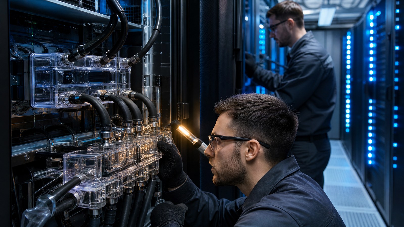
In direct-to-chip designs, a cold plate transfers heat from selected components to a circulating fluid loop. A coolant distribution unit, often called a CDU, can separate the technology cooling loop from facility water and manage heat exchange, pressure, and fluid conditions. This makes the physical heat path more layered than a rack served only by room air. Capacity planning therefore needs to include the rack, loop, distribution equipment, and facility interface together.
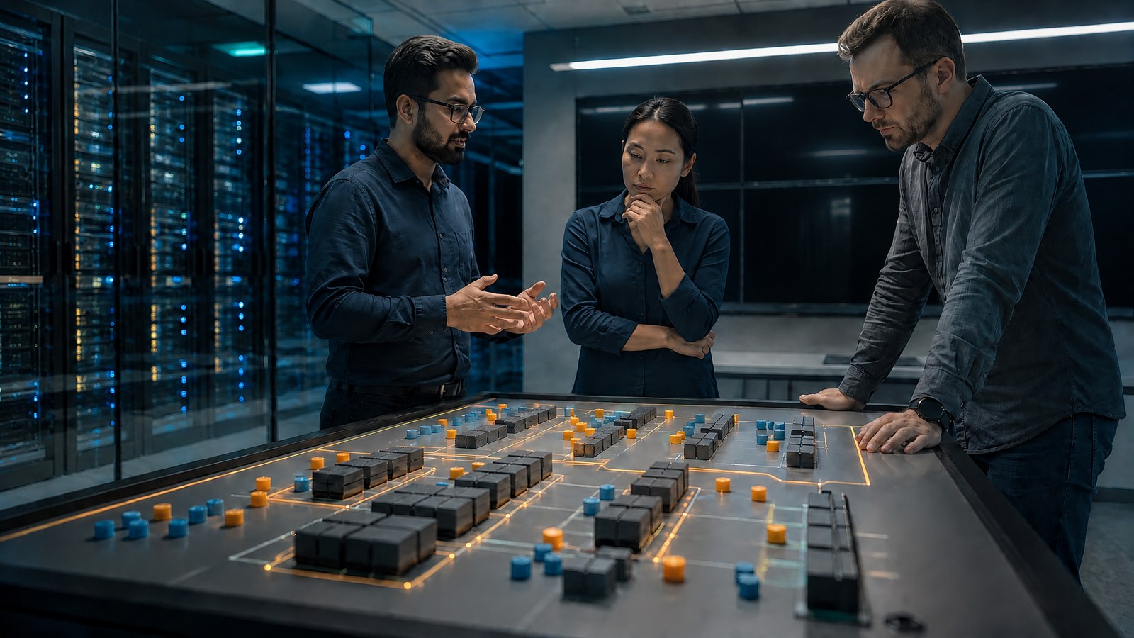
Higher equipment density does not erase spatial constraints. Water-cooled server racks can vary in footprint, and auxiliary distribution equipment needs room, access, and support. A design review should trace the maximum expected thermal load through every interface, while also checking power delivery, structural loading, cable routing, and technician access. Density is a property of a coordinated facility and equipment system, not simply a larger number printed on a rack plan.
Treat fluid quality as an operational requirement
Fluid loops contain materials, passages, filters, pumps, connectors, and cold plates that can be affected by contamination or incompatible chemistry. ASHRAE guidance discusses the relationship between microchannel dimensions and filtration, illustrating why maintenance choices cannot be separated from component requirements. The responsible practice is to use the equipment and loop specifications to define fluid, sampling, filtration, and replacement procedures rather than assuming that all water systems are interchangeable.
A filter protects downstream components but also adds pressure drop as it collects material. Finer filtration can provide greater protection for small passages while changing pumping and maintenance considerations. These are design and operations trade-offs, not universal settings. Keep records of fluid condition, filter state, pressure behavior, and interventions so abnormal changes can be distinguished from the expected service lifecycle and investigated before they affect equipment availability.
Make serviceability visible in the layout
A maintainable installation leaves technicians a clear, safe way to inspect couplings, isolate sections, replace components, and work around the rack without disturbing unrelated equipment. Service access should be assessed during layout planning, including the location of shutoffs, drains, connection points, containment, and lifting or handling needs. A compact aisle may appear efficient on a drawing while making routine maintenance slow or increasing the chance that a corrective action touches the wrong circuit.
Documented procedures should identify the equipment state before service begins, the isolation boundary, the required verification, and the condition for return to service. This is especially important when a rack contains both liquid and air-cooled components, because thermal behavior may change during partial shutdown. Training and change review should cover the physical configuration that teams actually operate. A generic mechanical procedure is not enough for a specific rack and loop design.
Plan failure response around isolation and detection
A fluid-related event is not one thing. It may involve loss of flow, pump degradation, an out-of-range temperature, a connector issue, a leak alarm, or loss of the facility-side heat-rejection path. Define the signals that distinguish these conditions and the automatic protections, such as workload throttling or shutdown, that are appropriate for the supported equipment. Avoid promising a single response that assumes every thermal event has the same cause.
Resilience depends on the isolation boundaries and the time available for intervention. A fault that can be confined to one loop has different consequences from a shared distribution interruption. Review whether redundant equipment shares a power source, control path, or maintenance dependency, because apparent duplication can still have common-mode weaknesses. The failure plan should include safe stop, notification, investigation, and controlled restart steps, with authority assigned for each decision.
Coordinate IT and facilities telemetry
The important signals span teams: equipment temperatures and throttling behavior on the IT side, and flow, pressure, supply and return temperatures, alarms, and equipment status on the facilities side. Correlating them can help locate whether a symptom starts at a server, rack, loop, CDU, or facility interface. Correlation does not establish causation by itself, so incident records should preserve timing, configuration changes, and actions taken alongside the telemetry.
Set alert priorities around customer and equipment risk, not merely around every sensor reading. A warning trend may call for planned maintenance; a loss of a protective function may call for immediate action. Thresholds, owners, escalation paths, and inhibition logic need review as the deployment expands. The goal is a shared operational picture that lets the right people act before thermal protection becomes an unplanned service interruption.
Adopt liquid cooling through controlled operational changes
Begin with a defined equipment scope, a documented cooling architecture, and acceptance criteria that include service procedures and alarm ownership. Verify the as-built loop against the design, capture component identifiers in the internal asset record, and establish baseline operating behavior before scaling. This does not remove uncertainty; it gives later decisions a reference point and prevents a small pilot’s assumptions from silently becoming a facility-wide operating model.
Use the site’s Cloud & Infrastructure coverage to keep infrastructure, capacity, and reliability discussions connected. The durable takeaway is not that liquid cooling is inherently simpler or riskier than air cooling. It changes where heat is managed and therefore changes the work required to maintain it. Teams that plan the physical interfaces, maintenance windows, telemetry, and isolation strategy can make that change intelligible instead of treating it as a specialist exception.
Source notes
Reporting record
techduopulse stores source destinations privately. Public notes remain non-clickable so every visitor journey stays on this website.
ASHRAE water-cooled servers white paper
Primary source · CDUs, filtration, components, and processesASHRAE data-center resources
Primary source · Data-center thermal and liquid-cooling resourcesInitial reviewed edition explains liquid-cooling operations with ASHRAE technical guidance on water-cooled server systems.