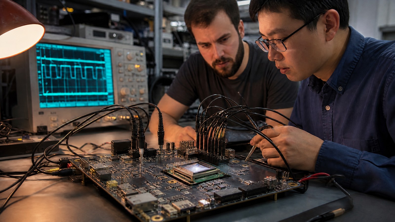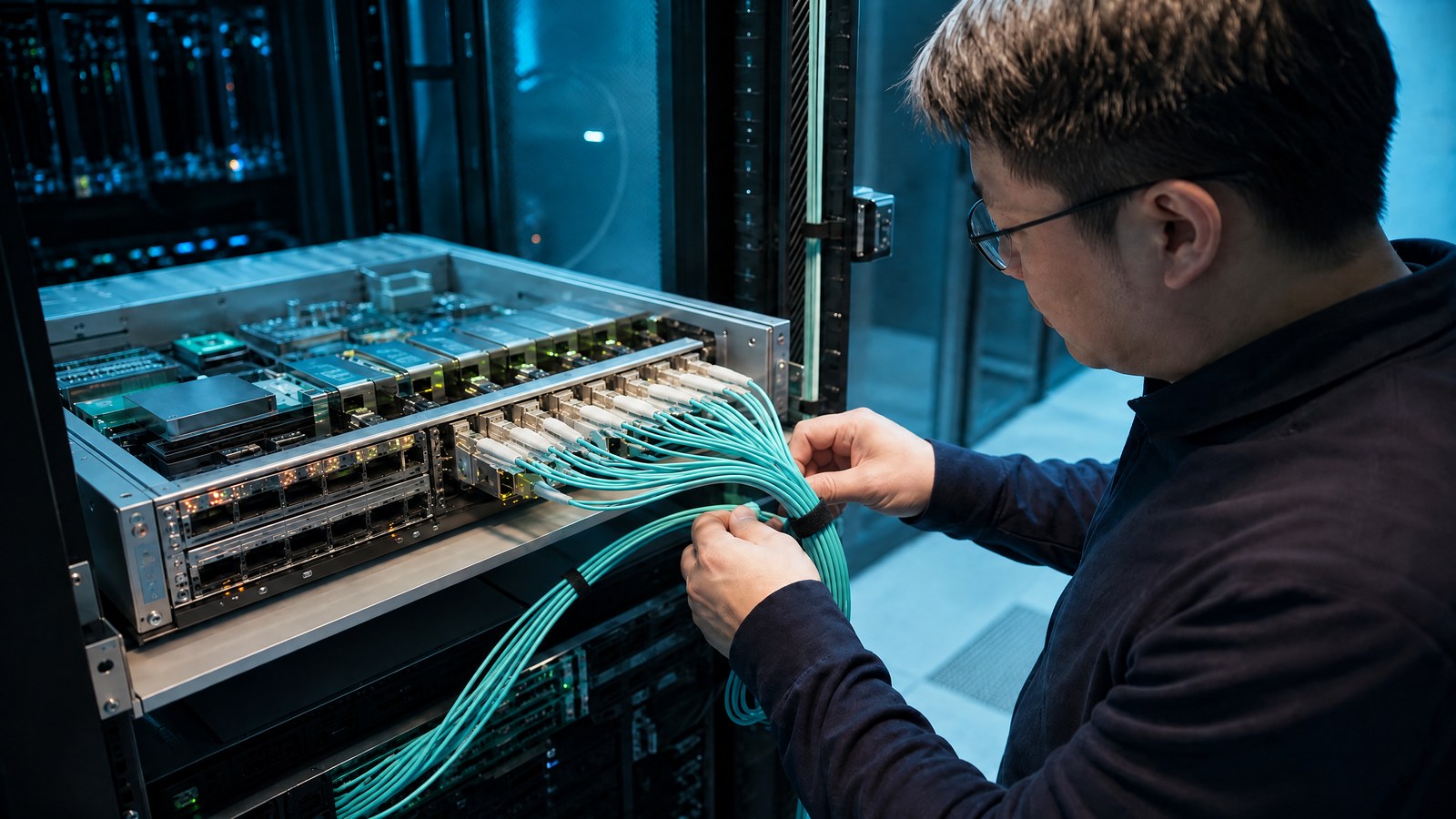
An Ethernet switch is already a meeting point for many fast links. In a conventional layout, electrical signals travel from the switch package across a board to pluggable optical modules at the equipment edge. Co-packaged optics, often shortened to CPO, brings optical conversion physically nearer to the switch silicon. The motivation is architectural rather than fashionable: shorter electrical paths may be easier to manage at very high signalling rates, but the new placement transfers complexity into the package and service model.
This article is part of the computer hardware technology guide library.
The pluggable module sets today’s boundary
A pluggable optical module is designed to be inserted at the faceplate of a switch or router. It presents an electrical interface to the host and an optical interface to fibre. That separation makes replacement and port-by-port configuration comparatively direct. It also means the board carries high-speed electrical channels between switching silicon and many module cages. At modest channel demands, that division is practical; at tougher ones, channel loss and equalisation become central design concerns.
Co-packaged optics changes the location of the optical engine, not the purpose of the network connection. The switch still sends and receives data; fibre still carries light between systems. What changes is the electrical distance before light is created or detected. The OIF’s co-packaged-module agreement addresses electro-optical-mechanical details, optical and copper cable attachment, management, and host interfaces. That breadth signals that a package-near optical design is a complete subsystem, not merely an alternative connector.
Why electrical reach becomes a design limit
Fast electrical signalling over a board encounters attenuation, reflections, crosstalk, and timing distortion. Transmitters and receivers can compensate for some impairment, but those techniques consume design margin and power. The exact limit depends on signalling method, materials, routing, connectors, and implementation. Moving the optical engine closer to the switch can shorten this electrical segment, potentially reserving more margin for the link that remains. It does not eliminate the need for careful channel engineering.
The benefit must be evaluated at system level. A shorter electrical route may reduce one source of difficulty while making optical attachment, module cooling, or repair more demanding. The OIF describes its 3.2 Tb/s agreement as targeting Ethernet switching applications and defining host, optical, electrical, opto-mechanical, and control interfaces. Standards work is valuable here because an optical architecture has to connect several disciplines and suppliers without leaving basic interfaces to undocumented assumptions.
What “co-packaged” actually means
In co-packaged optics, optical engines are integrated near the switch application-specific integrated circuit within a shared package or closely coupled assembly. An optical engine generally includes components that convert electrical signals to light and light back to electrical signals, along with coupling and control functions. This is different from simply placing a conventional pluggable module close to a switch. The packaging relationship is the defining feature, because it changes the electrical path and physical integration work.
Co-packaging does not require every implementation to share the same laser, fibre-attach, cooling, or maintenance architecture. The OIF agreement documents both optical and copper cable attachment formats and a management interface for a defined module. Such details should discourage overgeneralisation. CPO is a family of system choices constrained by interfaces and assembly methods. Its technical case should be made for a particular switch topology and operating environment, not treated as a universal replacement for pluggable optics.
The package becomes an optical workplace
Optics near a powerful switch must coexist with heat, tight mechanical tolerances, and many fibre connections. Fibre alignment and strain management become part of package and chassis design. Optical components may have temperature-sensitive behaviour, while the switching device may be a substantial heat source. Engineers must arrange the optical, electrical, thermal, and mechanical paths together. A design that shortens a board trace but obstructs cooling or makes fibre handling fragile has shifted rather than solved the systems problem.
This is why implementation agreements specify more than data rates. The OIF document defines electro-optical-mechanical aspects and includes control and management interfaces. Those elements establish a baseline vocabulary for physical form, operation, and interoperability. They do not certify every system’s reliability or maintenance process. Operators and equipment designers still need to qualify cable handling, contamination control, thermal excursions, fault detection, and replacement procedures for their own product architecture.
Maintenance is a core trade-off
Faceplate modules create a familiar service boundary: a port component can often be exchanged without disturbing the switch package. Bringing optics inward can make that boundary less obvious. An optical, electrical, or thermal failure may require a different diagnostic path and a different replaceable unit. The practical consequence is not that CPO is unserviceable; it is that serviceability must be designed deliberately, including access, isolation, spare strategy, and signals that distinguish a photonic fault from a switching fault.
External laser arrangements, detachable cable assemblies, and management standards are examples of design choices that can shape that trade-off. Their appropriateness depends on the required density, environmental constraints, fault model, and operational workflow. The careful comparison is therefore between complete platform designs, not between a single CPO benefit and a single pluggable benefit. Interoperable interface definitions can help, but they do not substitute for proving that an assembled system can be installed, monitored, and repaired safely.
Questions that keep the decision grounded
Start by mapping the signal path: where does the electrical channel begin, where does it end, and what channel impairment must the system tolerate? Then map the physical path: where are fibres attached, how are they protected, and which part of the machine is replaceable? These questions make the claimed advantage testable without requiring a date-sensitive market forecast. They also make room for conventional pluggables where their service boundary or ecosystem fit is the better engineering choice.
Finally, separate standardisation from deployment proof. An OIF implementation agreement can define an interoperable module interface, and that is meaningful infrastructure. It does not establish that every facility should adopt the architecture or that every workload benefits equally. Co-packaged optics is moving closer to switches because electrical distance is becoming a prominent constraint in some designs. Whether it belongs in a given system depends on the whole link: performance, power, cooling, fibre practice, diagnostics, and operations.
Source notes
Reporting record
techduopulse stores source destinations privately. Public notes remain non-clickable so every visitor journey stays on this website.
OIF co-packaged module implementation agreement
Primary source · Electro-optical-mechanical scope and cable attachment formatsOIF co-packaging interface overview
Primary source · Ethernet-switching target, host interfaces, management, and interoperabilityImage updated: embedded writing removed; article content and factual claims unchanged.